Wire electric discharge machine and automatic programming device for wire electric discharge machine

Active Publication Date: 2014-01-16
FANUC LTD
View PDF8 Cites 26 Cited by
  • Summary
  • Abstract
  • Description
  • Claims
  • Application Information

AI Technical Summary

Benefits of technology

[0035]According to the present invention, it becomes possible to provide a wire electric discharge machine and an automatic programming device for a wire electric discharge machine that can arbitrarily set a place where attachments are deposited and can deposit attachments in a minimal amount necessary to fix a core to a workpiece base material.
[0036]In addition, in the present invention, attachments can be deposited in a minimal amount necessary to fix a core to a workpiece base material and it is possible to solve the problems described above that possibly occur upon striking off a core. Still in addition, in the present invention, a junction of sides and a position of the center of gravity of a machined object are calculated from a machining shape using an automatic programming device and the like and it is possible to automatically set a position where attachments are deposited, so that there is almost no burden on an operator.
[0037]In addition, in the present invention, a

Problems solved by technology

Accordingly, with this technique, it becomes difficult to strike off the core after electric discharge machining because the core and the workpiece base material are firmly bonded by the attachments containing brass of the wire electrode that are deposited all around the machining groove.
Therefore, when trying to strike off a core forcibly, a variety of problems are prone to occur, such as, in a case of a small core, that there is a possibility of damaging a workpiece base material by hitting the workpiece base material by mistake, that there is a possibility of hitting many times because a core does not easily fall, thereby damaging a workpiece base material due to misalignment of the core, and that there is a possibility of hitting many times because a core does not easily fall, thereby disabling later machining d

Method used


Image

  • Wire electric discharge machine and automatic programming device for wire electric discharge machine
  • Wire electric discharge machine and automatic programming device for wire electric discharge machine
  • Wire electric discharge machine and automatic programming device for wire electric discharge machine

Examples


Example

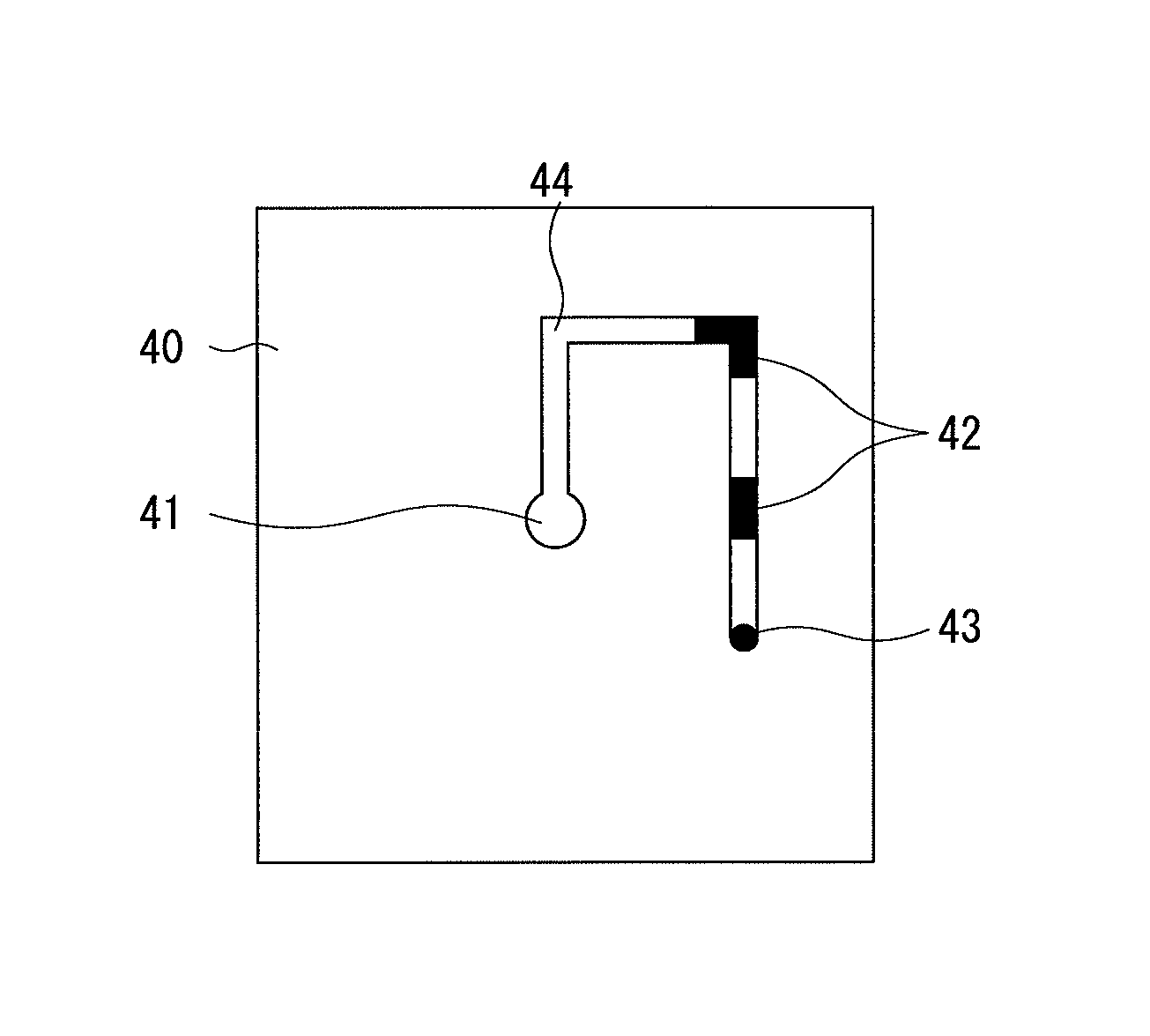
[0055]FIGS. 1A through 1C are diagrams to illustrate a first embodiment of a wire electric discharge machine according to the present invention in which a core is held with a workpiece base material.

[0056]With a wire electric discharge machine, electric discharge machining is carried out by relatively moving a wire electrode 43 and a workpiece base material 40 from a machining start hole 41. Over a predetermined range of a machining groove 44 in the workpiece base material 40, attachments containing brass derived from the wire electrode 43 are attached and deposited to the machining groove 44 formed in the workpiece base material 40 by the attachment / deposition unit, thereby forming a bridge.

[0057]The place where attachments are attached and deposited (attachment / deposition position) may also be set automatically utilizing a predetermined region including at least one of an intersection of a straight line and a straight line, an intersection of a straight line and a curved line, or ...

Example

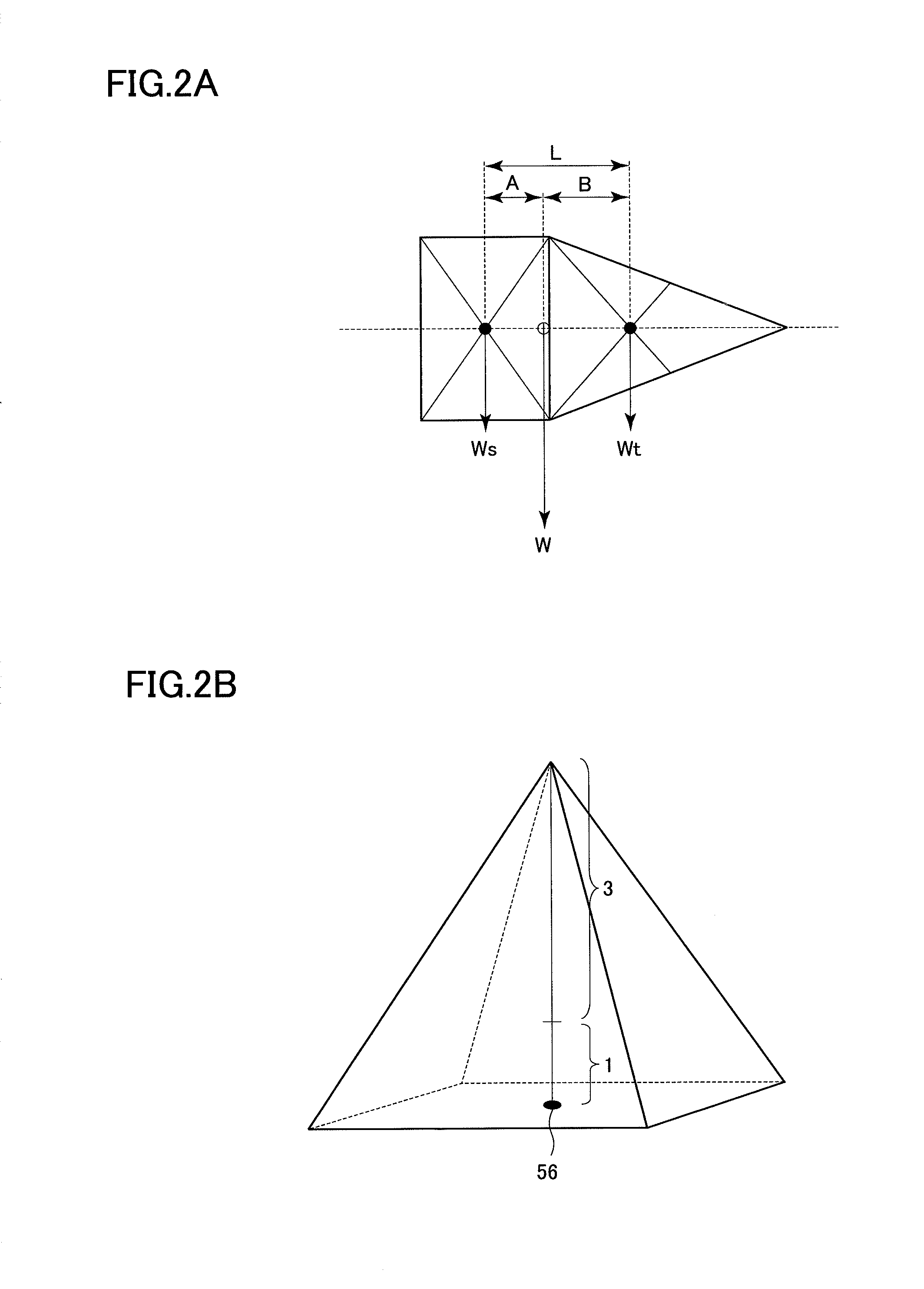
[0061]FIGS. 2A and 2B are diagrams to illustrate a second embodiment of a wire electric discharge machine according to the present invention in which a position of the center of gravity of the core, which is information necessary for automatic setting of a place where attachments are attached, is calculated.

[0062]An example of a core illustrated in FIG. 2A has a shape (composite core shape) formed by combining a quadrilateral shaped portion on the left side and a triangular shaped portion on the right side. The quadrilateral shaped portion has a weight of Ws and a position of the center of gravity thereof is represented by “” in the quadrilateral shape, and the triangular shaped portion has a weight of Wt and a position of the center of gravity thereof is represented by “” in the triangular shape, as shown in FIG. 2A. A distance between the position of the center of gravity of the quadrilateral shaped portion and the position of the center of gravity of the triangular shaped porti...

Example

[0072]FIGS. 3A through 3G are diagrams to illustrate a third embodiment of the present invention in which a position where attachments are deposited is set for each predetermined distance from the position of the center of gravity of a graphic, for each predetermined distance from a predetermined position including an intersection of a straight line and a straight line, an intersection of a straight line and a curved line, or a point at which curvatures in front and behind thereof vary (as described above, the intersection or the point is referred to as a junction) defining a machining path, or for each predetermined distance from an approach end point.

[0073]In case of setting a place where attachments are attached based on the position of the center of gravity of a planar figure, as illustrated in FIGS. 3A through 3C, attachment attaching places 62 are set on intersections of two straight lines 61 each passing through, and intersecting at a right angle, at a position 60 of the cent...


PUM

PropertyMeasurementUnit
Shapeaaaaaaaaaa
Gravityaaaaaaaaaa
Distanceaaaaaaaaaa

Abstract

In a wire electric discharge machine or an automatic programming device for a wire electric discharge machine, in which a core is held with a workpiece base material by attaching brass contained in a wire electrode to the machining groove during machining, an attachment/deposition region where machining chips containing brass produced during machining are attached and deposited to the workpiece is set based on a machining shape obtained from a machining program and the machining chips containing brass produced during machining are attached and deposited according to the set attachment/deposition region.

Description

BACKGROUND OF THE INVENTION[0001]1. Field of the Invention[0002]The present invention relates to a wire electric discharge machine and an automatic programming device for a wire electric discharge machine that have an anti-drop function for a workpiece by attaching an electrode component to the workpiece.[0003]2. Description of the Related Art[0004]Descriptions are given to machining in a case of carrying out die machining with a wire electric discharge machine using FIG. 8 taken from above of a workpiece.[0005]The machining starts from a machining start hole 15 with a wire electric discharge machine. In a machining path through which a wire electrode 13 has gone, a machining groove 14 is formed. In a die machining method in prior art, in a case of carrying out machining to produce a core 12 using a wire electric discharge machine, a residual stock removal 11 is generally provided in a workpiece base material 10 during rough machining and the core 12 is cut off during a post treatme...

Claims


Application Information

Patent Timeline
IPC IPC(8): B23H1/04
CPCB23H1/04B23H7/02B23H11/00B23H7/065B23H7/20G05B19/40931G05B2219/45221Y02P90/02
Inventor YAMAOKA, MASAHIDEARAKAWA, YASUO
Owner FANUC LTD
Why Eureka
Try Eureka