
Rotor for ipm motor, and ipm motor equipped with same

a technology of ipm motor and ipm motor, which is applied in the direction of magnetic circuits characterised by magnetic materials, magnetic circuit shapes/forms/construction, magnetic circuit rotating parts, etc., can solve the problems of field-weakening control reducing the torque of the motor, limited influence, and increased manufacturing costs of the motor, so as to increase the output torque in the high rotation range, increase the maximum rotation frequency, and increase the output torque. the effect of high rotation rang

Active Publication Date: 2014-01-16
NISSHIN STEEL CO LTD
View PDF10 Cites 11 Cited by
  • Summary
  • Abstract
  • Description
  • Claims
  • Application Information

AI Technical Summary

Benefits of technology

The present invention provides a rotor and an IPM motor that can increase the output torque in a high rotation range and the maximum rotational speed. The rotor uses a specific base steel sheet with a high magnetic flux density and coercivity, which results in increased output torque and maximum rotation frequency. The rotor is also formed by laminating base steel sheets with a yield strength of 750 N / mm2 or more, which prevents damage from centrifugal force and allows for a narrower bridge portion, reducing magnetic flux leakage and increasing motor flexibility. The permanent magnets can also be miniaturized, reducing motor cost.

Problems solved by technology

The iron core on the rotor side is subject to minor influence of the AC magnetic field generated from the stator side, but this influence is limited.
However, the same electromagnetic steel sheets as the stator side are also used for the iron core on the rotor side because the product yield of the electromagnetic steel sheets drop and manufacturing costs of the motor increase if the electromagnetic steel sheets are used only for the stator.
Although operation in a high-speed rotation range becomes possible, the field-weakening control decreases the motor torque because power is used for cancelling the magnetic flux of the permanent magnet.
On the other hand, even if the IPM motor is miniaturized, there is a problem where the centrifugal force that acts upon the permanent magnet embedded in the rotor increases to damage the rotor if the rotational speed of the rotor is increased so as to obtain a torque equivalent to or higher than conventional motors.
In this way, an attempt is made to obtain higher torque by increasing rotational speed using the conventional rotor iron core made of electromagnetic steel sheets when an IPM motor is miniaturized, there is a limit on increasing the rotational speed because there are problems where torque decreases in the high-speed rotation range even if field-weakening control is performed, and the rotor could be damaged by the centrifugal force that acts on the permanent magnet.

Method used

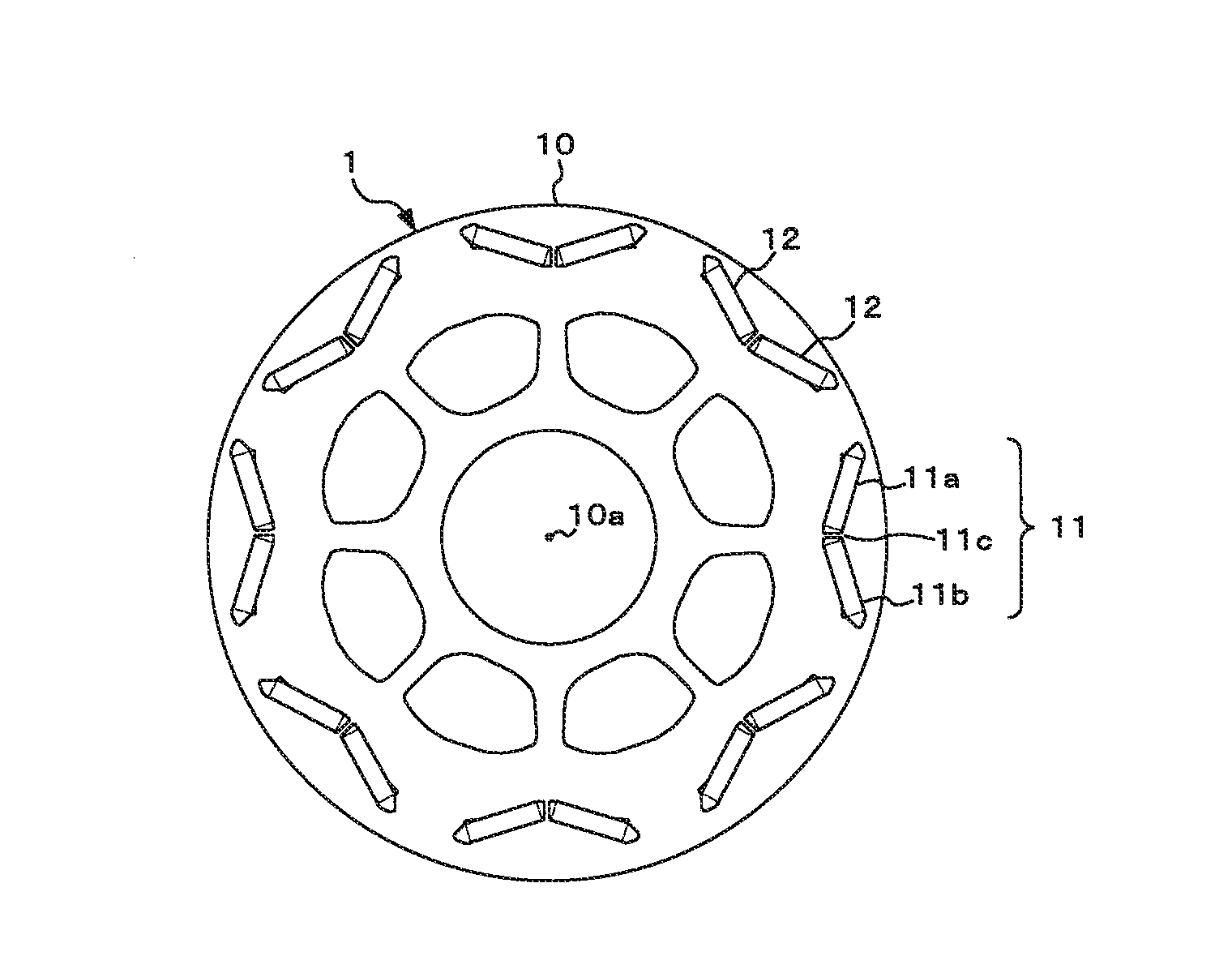
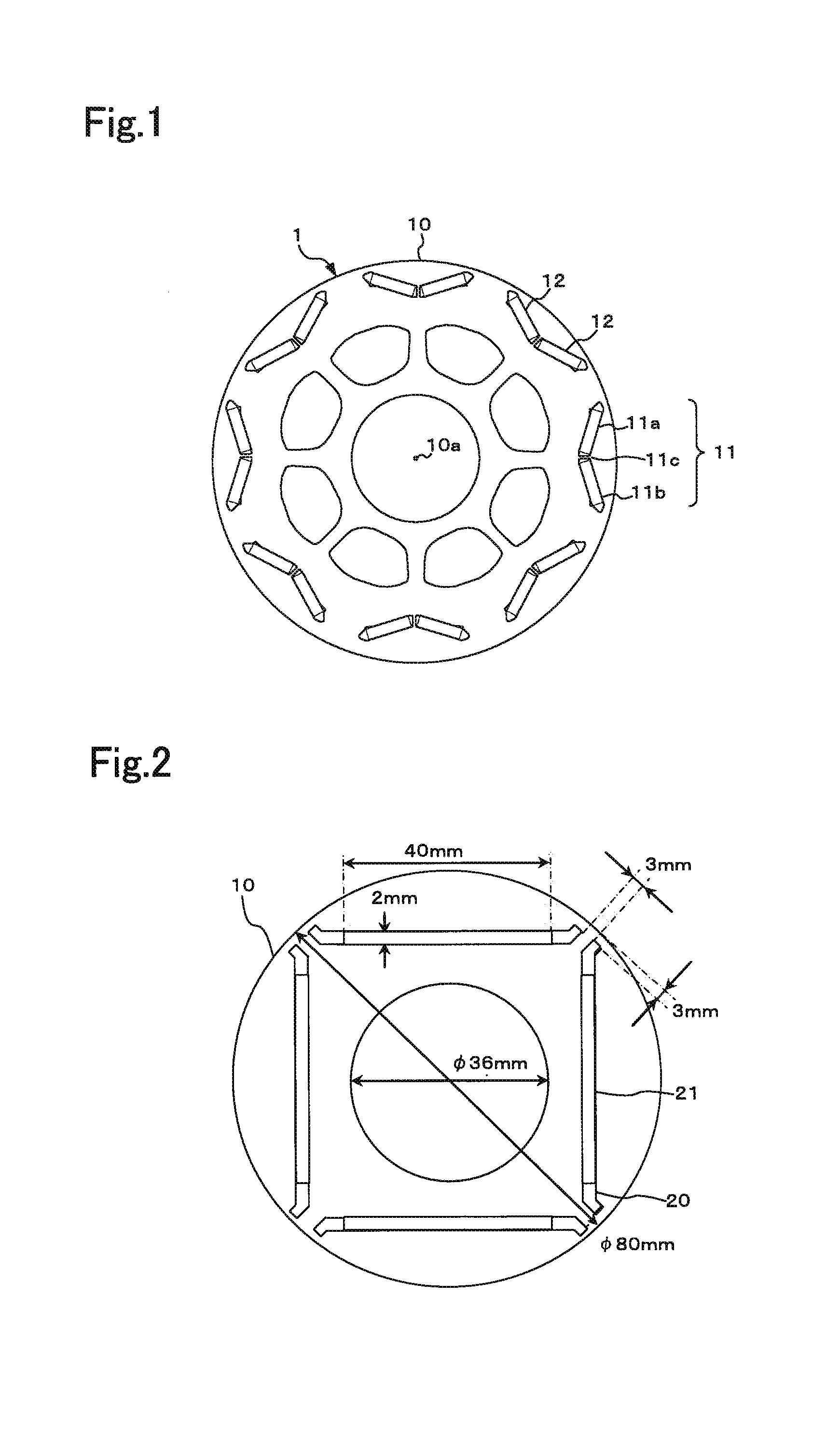
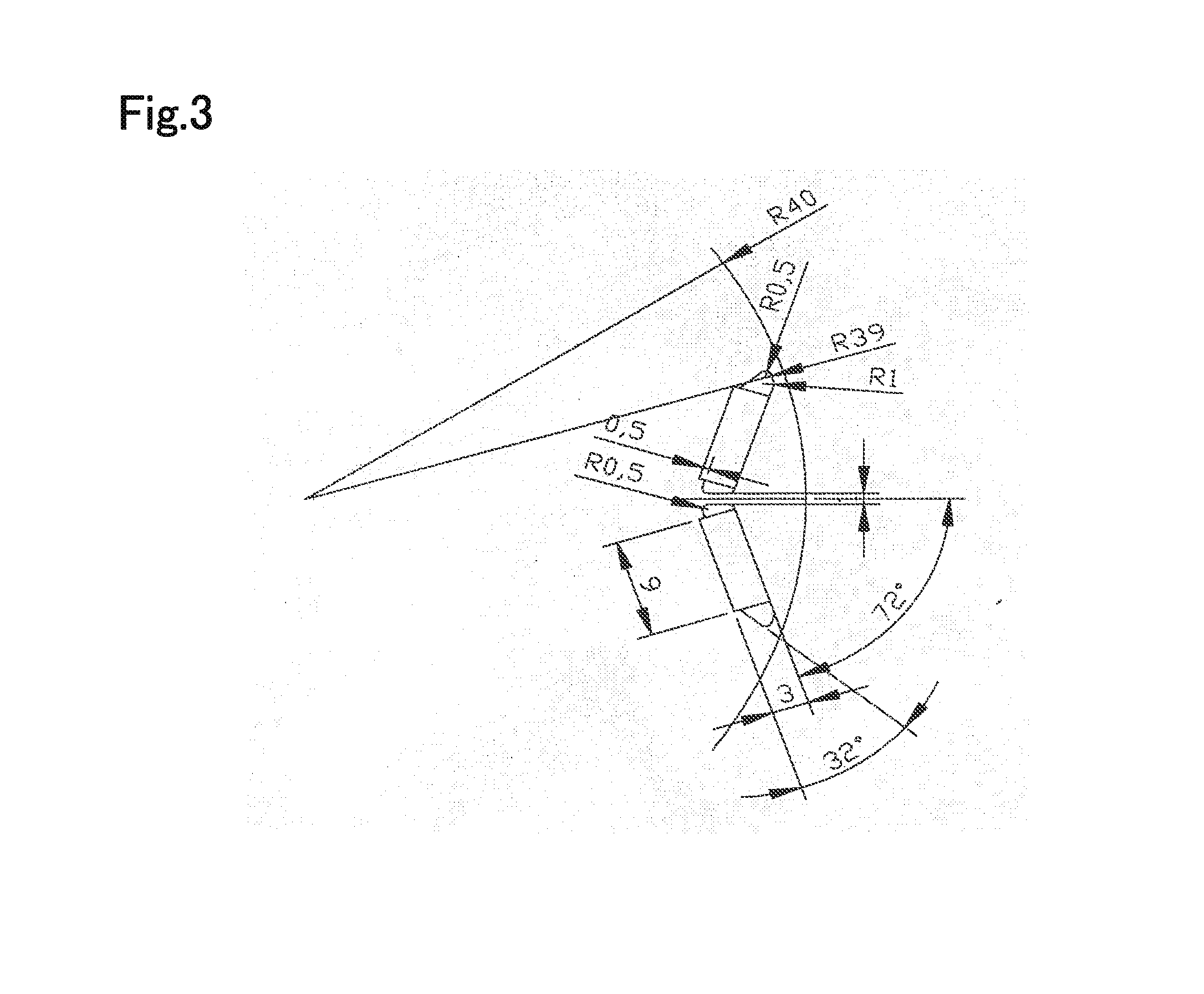

Image

  • Rotor for ipm motor, and ipm motor equipped with same
  • Rotor for ipm motor, and ipm motor equipped with same
  • Rotor for ipm motor, and ipm motor equipped with same

Examples


examples

[0039]The present inventors manufactured base steel sheets of the rotor iron core 10 by the following manufacturing method A using each steels having the component compositions shown in Table 1.

Manufacturing Method A

[0040]Each of the steels having the component compositions shown in Table 1 were melted in a vacuum, continuous cast slabs thereof were heated to 1250° C., finish-rolled at 950° C., and wound up at 560° C. As result hot-rolled steel sheets with a sheet thickness of 1.8 mm were obtained. After performing acid-cleaning for the hot-rolled steel sheets, cold-rolled steel sheet strips with a sheet thickness of 0.35 mm were obtained by performing cold rolling once (final reduction rate: approximately 81%). Then tension annealing processing (tensile strength: 100 N / mm2) was performed on the obtained cold-rolled steel sheet strips by threading the strips through a continuous furnace set at 400° C. for 60 seconds. Then an insulation film, with a semi-organic composition having a ...


PUM


Abstract

A rotor iron core is used, which is formed by laminating a base steel sheets with a magnetic flux density (B8000) of 1.65 T or more as measured at a magnetic field strength of 8000 A / m and a coercivity of 100 A / m or more.

Description

TECHNICAL FIELD[0001]The present invention relates to a rotor for an interior permanent magnet motor (hereafter “IPM motor”) that is used for electric vehicles, hybrid vehicles and machine tools, for example, and an IPM motor equipped with the rotor.BACKGROUND ART[0002]Generally, IPM motors, which use expensive permanent magnets, have high cost but higher efficiency than induction motors. Therefore IPM motors are widely used for driving motors and power generating motors for hybrid vehicles and electric vehicles, and motors for home electric appliances, various machine tools and industrial machines.[0003]An iron core of IPM motors is constituted by a stator and a rotor. Since an AC magnetic field is directly applied to the iron core on the stator side via windings, the iron core on the stator side must have high magnetic permeability and high volume resistivity so as to reduce iron loss. Hence electromagnetic steel sheets, of which the soft magnetic characteristics have been improve...

Claims


Application Information

Patent Timeline
IPC IPC(8): H02K1/27H02K1/02
CPCH02K1/272H02K1/02H02K1/2766H02K2213/03Y02T10/64H02K1/22H02K1/27H02K1/04
Inventor IWATSU, TOMONAGAKATAGIRI, YUKIOFUJIWARA, SUSUMUMORIKAWA, SHIGERU
Owner NISSHIN STEEL CO LTD
Learn More