Light source module and light source assembly having the same

a technology of light source module and light source assembly, which is applied in the direction of lighting and heating apparatus, lighting support devices, instruments, etc., can solve the problems of reducing display quality or durability, reducing or effectively preventing the reduction of heat generated by the light source unit, and difficulty in so as to achieve the reduction of the area occupied by the light emitting part, enhancing light efficiency, and reducing the size of the bezel

Active Publication Date: 2014-01-16
SAMSUNG DISPLAY CO LTD
View PDF8 Cites 11 Cited by
  • Summary
  • Abstract
  • Description
  • Claims
  • Application Information

AI Technical Summary

Benefits of technology

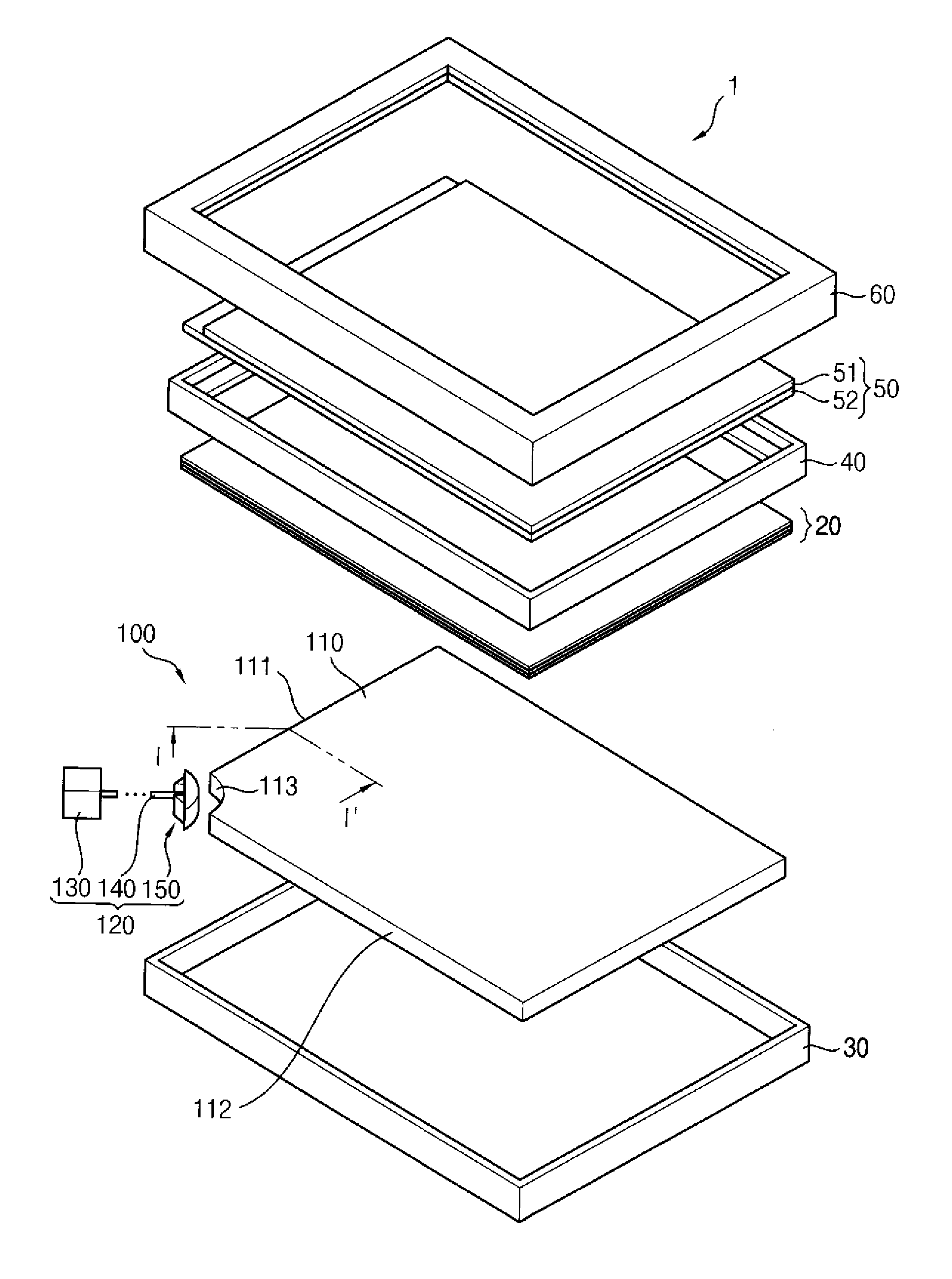
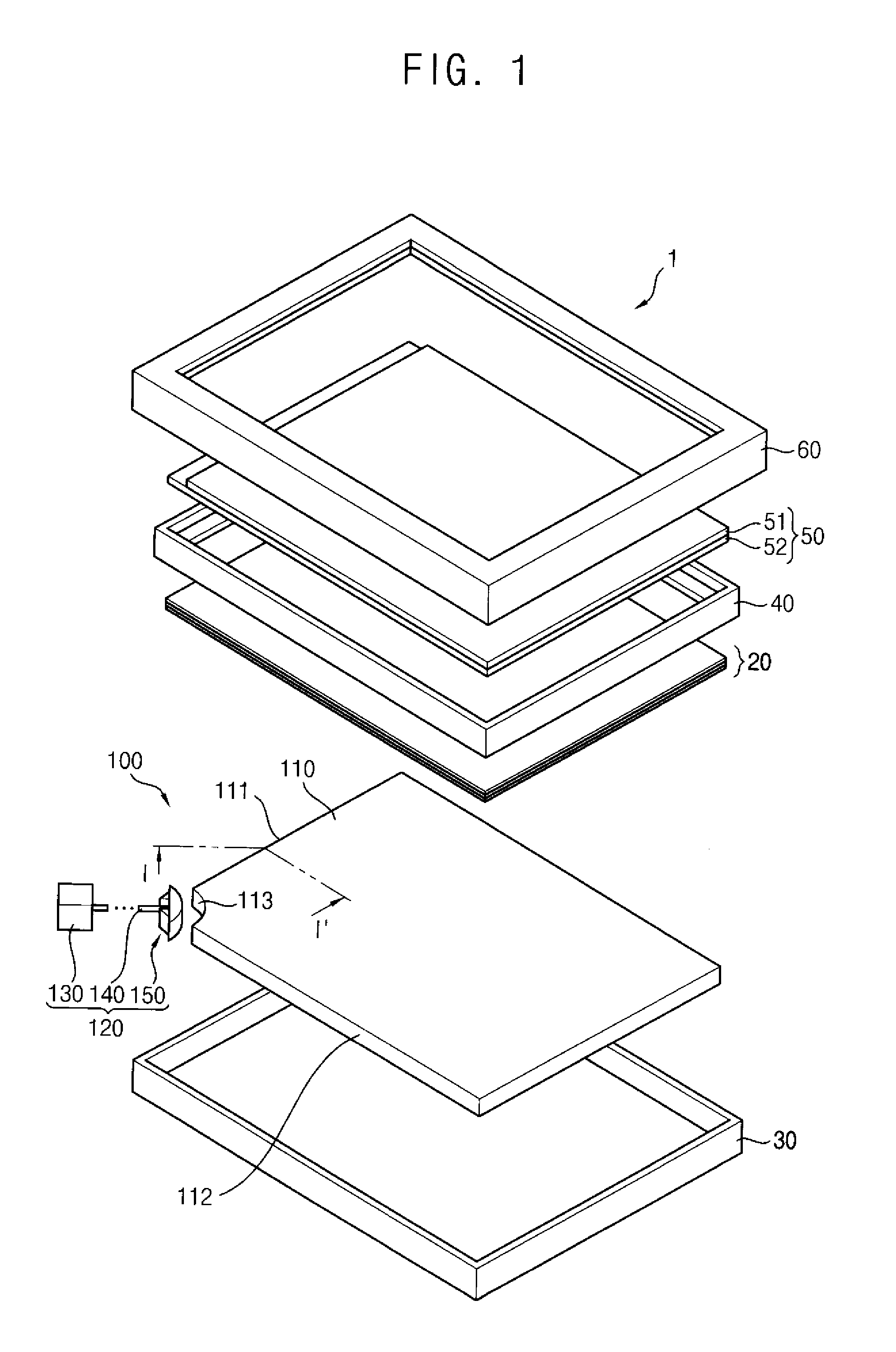
[0033]In addition, the incident surface of the light guide plate is concaved with the curved shape and the light emitting part is disposed at the concaved portion of the incident surface. Thus an area occupied by the light emitting part may be minimized both when the light emitting part is disposed at the corner portion of the light guide plate and when the light emitting part is disposed at the side surface of the light guide plate. Thus, an area of a bezel of a display apparatus may be reduced and minimized.
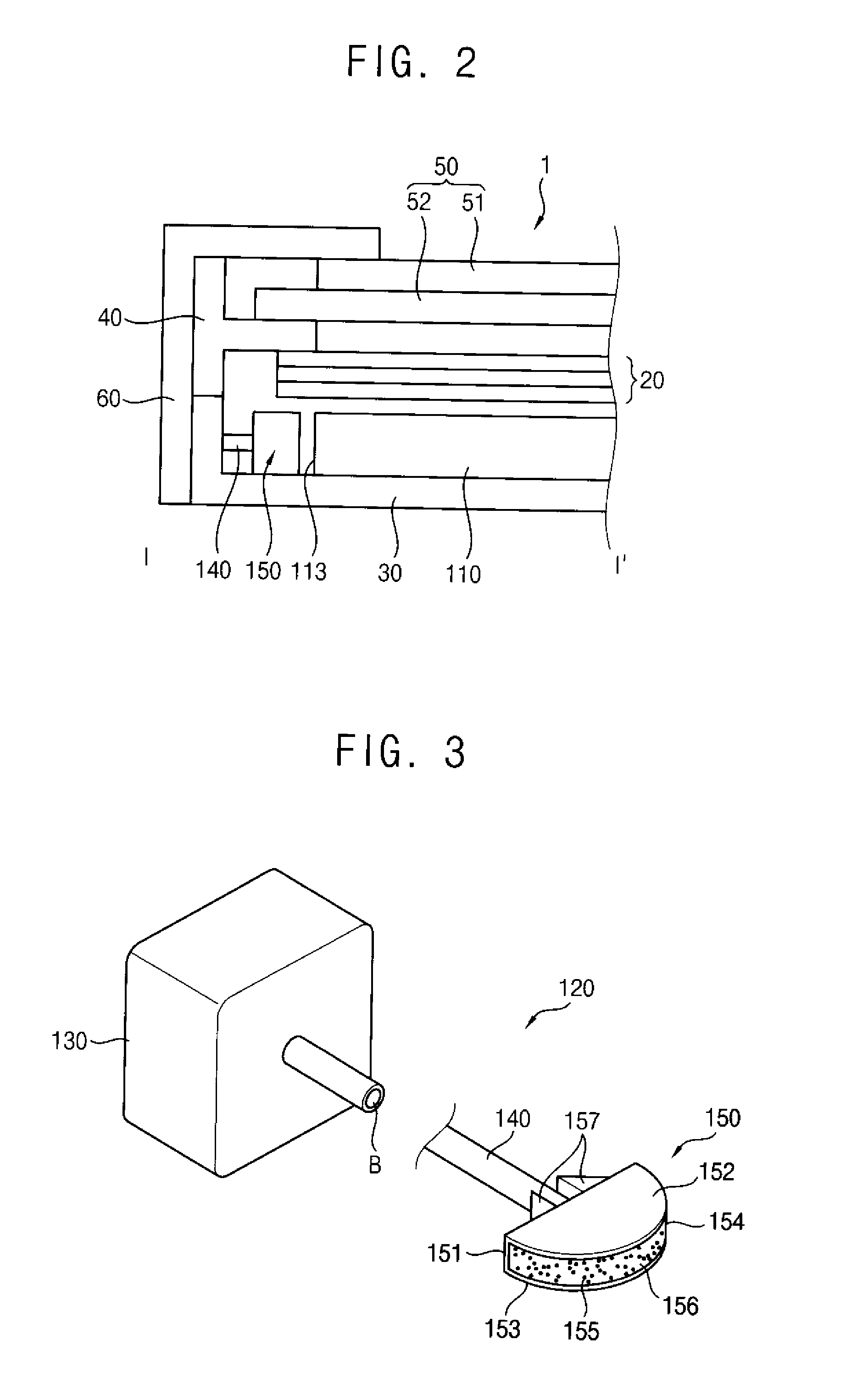
[0034]In addition, the light source part may merely emit the blue light, and the light emitting part may include the light converting material to convert the blue light to the white light, so that the light efficiency may be enhanced and a coupling between the light emitting part and the light transmitting part may be enhanced.
[0035]Alternatively, even where the light source part emits the red, green and blue lights, the light emitting part may mix the red, green and blue lights to make the white light and emits the white light, so that the light transmitting part merely transmits one color light. Thus the coupling between the light emitting part and the light transmitting part may be more enhanced.

Problems solved by technology

Further, even though the light source unit is merely disposed at the edge or the corner of the light guide plate, an additional space for the light source unit and for a driving unit for the light source unit is necessary, such that it may be difficult to reduce a size of the bezel.
In addition, a decrease in display quality or durability due to heat generated from the light source unit is reduced or effectively prevented.

Method used


Image

  • Light source module and light source assembly having the same
  • Light source module and light source assembly having the same
  • Light source module and light source assembly having the same

Examples


Embodiment Construction

[0045]It will be understood that when an element or layer is referred to as being “on,”“connected to” or “coupled to” another element or layer, the element or layer can be directly on, connected or coupled to another element or layer or intervening elements or layers. In contrast, when an element is referred to as being “directly on,”“directly connected to” or “directly coupled to” another element or layer, there are no intervening elements or layers present. As used herein, connected may refer to elements being physically and / or electrically connected to each other. Like numbers refer to like elements throughout. As used herein, the term “and / or” includes any and all combinations of one or more of the associated listed items.

[0046]It will be understood that, although the terms first, second, third, etc., may be used herein to describe various elements, components, regions, layers and / or sections, these elements, components, regions, layers and / or sections should not be limited by t...


PUM


Abstract

A light source module includes a light source unit which generates a light; a light emitting part spaced apart from the light source unit and comprising a light emitting surface; and a light transmitting part which transmits the light generated by the light source unit to the light emitting part. The light emitting part emits the light transmitted by the light transmitting part, through the light emitting surface.

Description

[0001]This application claims priority to Korean Patent Application No. 10-2012-0075056, filed on Jul. 10, 2012, and all the benefits accruing therefrom under 35 U.S.C. §119, the contents of which in its entirety is herein incorporated by reference.BACKGROUND[0002]1. Field[0003]Exemplary embodiments of the invention relate to a light source module, and a light source assembly having the light source module. More particularly, exemplary embodiments of the invention relate to a light source module used for a display apparatus, and a light source assembly having the light source module.[0004]2. Description of the Related Art[0005]A display apparatus includes a display panel displaying an image, and a light source assembly providing a light to the display panel. An edge-illumination type light source assembly in which a light source unit is disposed at an edge of a light guide plate is normally used for the display apparatus, to decrease a thickness of the display apparatus.[0006]Furthe...

Claims


Application Information

Patent Timeline
Patent Type & Authority Applications(United States)
IPC IPC(8): F21V8/00F21V13/14F21V9/16F21V9/00F21V13/08
CPCG02B6/0066F21V9/00F21V13/08F21V9/16G02B6/0005F21V13/14Y10S977/774Y10S977/95B82Y20/00G02B6/0021G02B6/0023G02B6/0028G02B6/0068F21V9/30G02B6/0013
Inventor PARK, CHAN-JAEBAEK, SEUNG-HWANHAN, YOUN-HONAM, SEOK-HYUNLEE, SANG-WONLEE, YOUNG-KEUN
Owner SAMSUNG DISPLAY CO LTD
Why Eureka
Try Eureka