Transmission apparatus for a wireless device

a wireless device and transmission apparatus technology, applied in the field of radio frequency identification systems, can solve the problems of inability to transmit arbitrary signals, inability to backscatter signals of arbitrary complex types, and inability to use arbitrary complex types of modulations in current rfid backscattering systems

Active Publication Date: 2014-01-16
DRNC HLDG INC
View PDF11 Cites 46 Cited by
  • Summary
  • Abstract
  • Description
  • Claims
  • Application Information

AI Technical Summary

Problems solved by technology

However, arbitrary complex type modulations are generally not used in current RFID backscattering systems.
There are several problems with prior tag transmission apparatus.
For example, systems such as that proposed by Thomas et al. are limited in the nature of signals that they can backscatter.
That is, any arbitrary signal cannot be transmitted.

Method used


Image

  • Transmission apparatus for a wireless device
  • Transmission apparatus for a wireless device
  • Transmission apparatus for a wireless device

Examples


Embodiment Construction

[0033]In the following description, details are set forth to provide an understanding of the invention. In some instances, certain software, circuits, structures and methods have not been described or shown in detail in order not to obscure the invention. The term “apparatus” is used herein to refer to any machine for processing data, including the systems, devices, and network arrangements described herein. The term “wireless device” is used herein to refer to RFID tags, RFID transponders, cellular telephones, smart phones, portable computers, notebook computers, or similar devices. The present invention may be implemented in any computer programming language provided that the operating system of the data processing system provides the facilities that may support the requirements of the present invention. Any limitations presented would be a result of a particular type of operating system or computer programming language and would not be a limitation of the present invention. The p...


PUM


Abstract

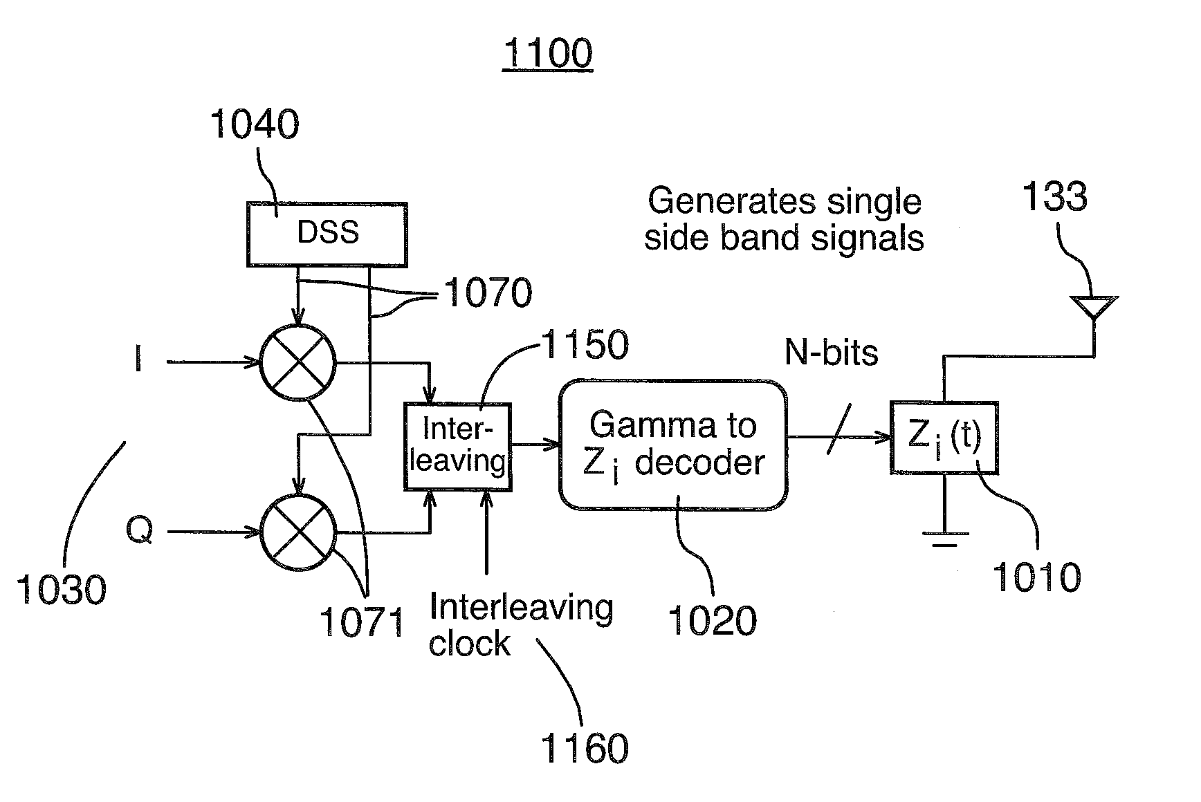
A transmission apparatus for a wireless device, comprising: an antenna for receiving an original signal and for backscattering a modulated signal containing information from the wireless device; a variable impedance coupled to the antenna, the variable impedance having an impedance value; and, a decoder coupled to the variable impedance for modulating the impedance value, and thereby a backscattering coefficient for the antenna, in accordance with the information to generate the modulated signal.

Description

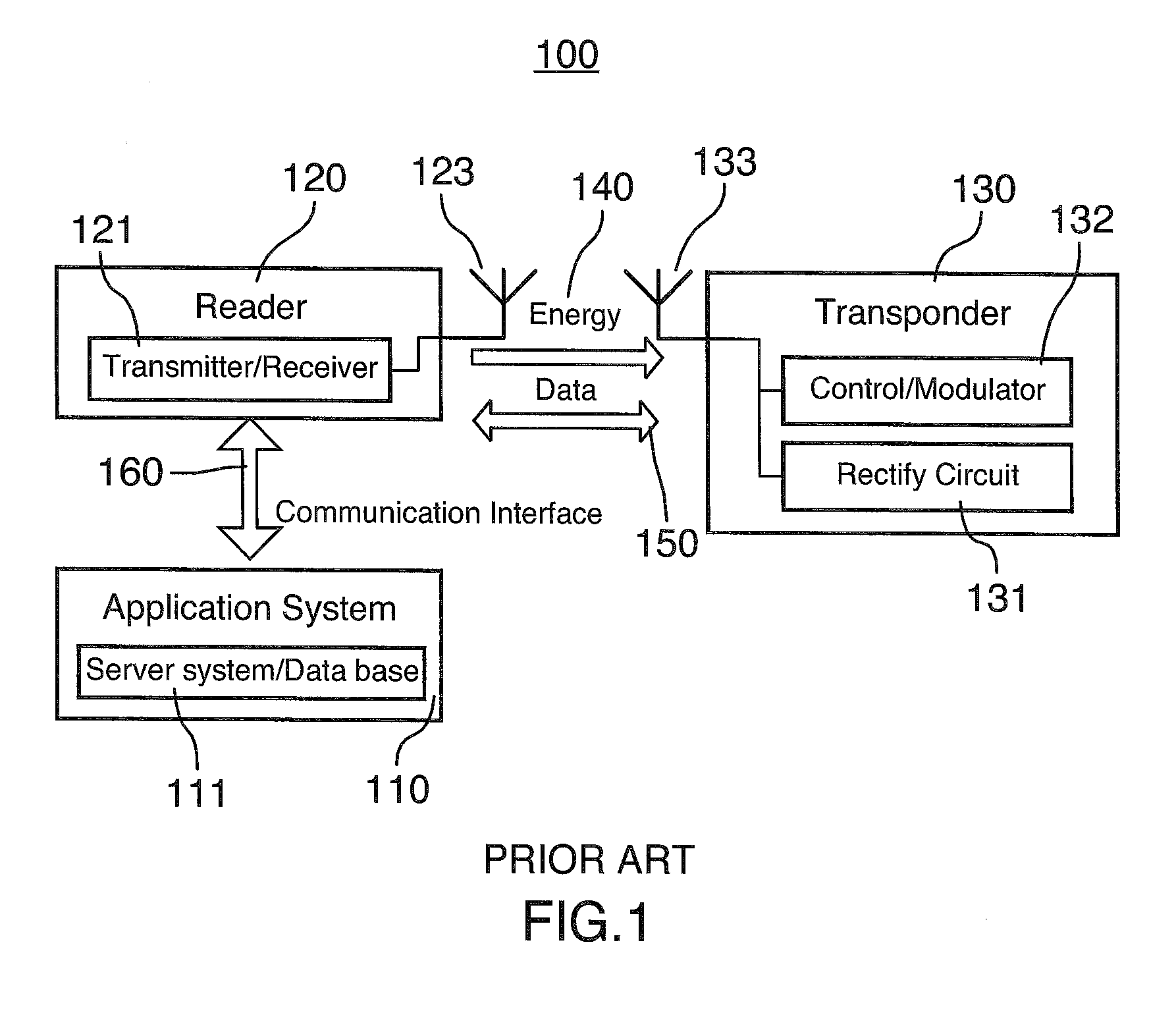
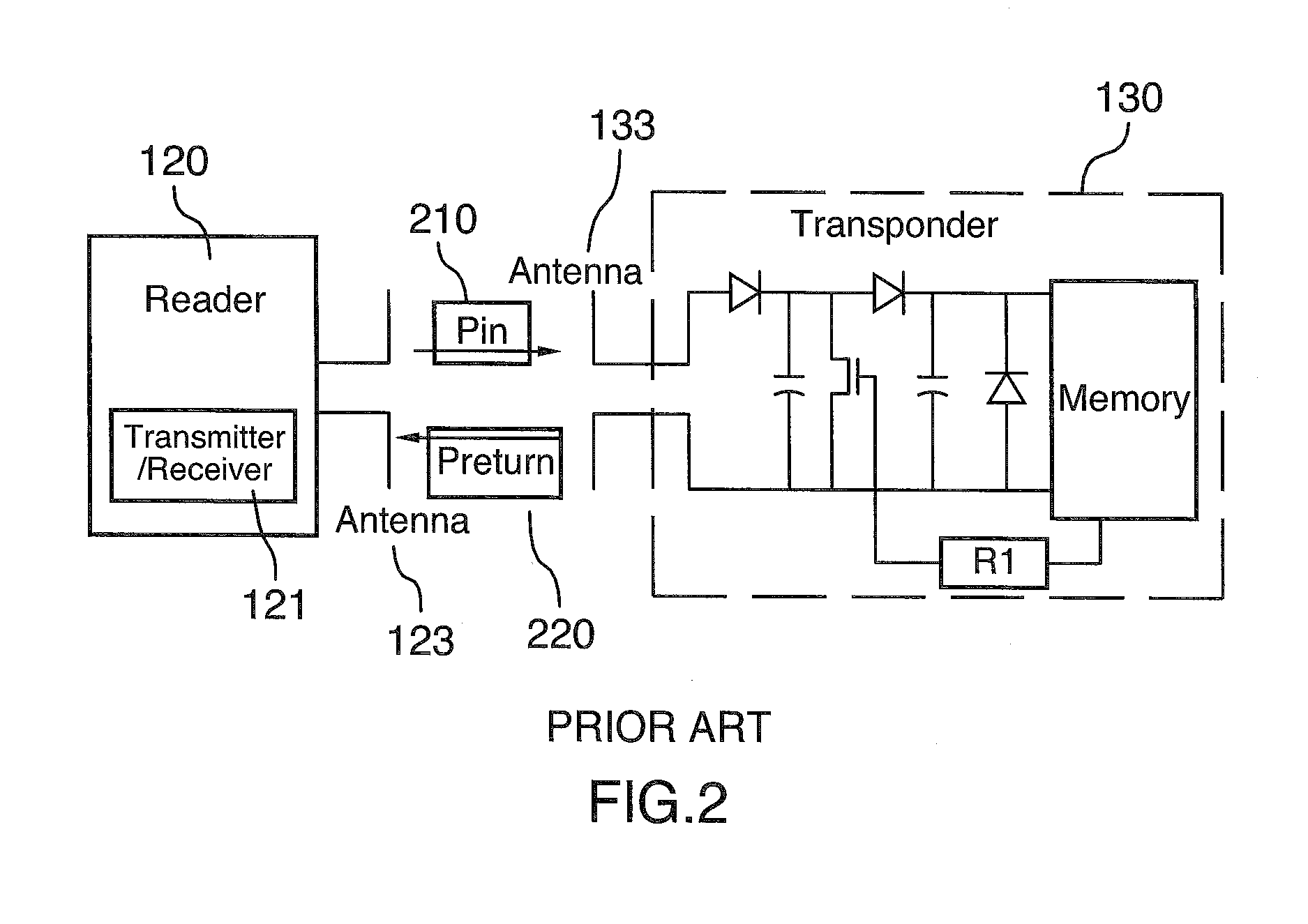
[0001]This application claims priority from U.S. Provisional Patent Application No. 61 / 670,259, filed Jul. 11, 2012, and incorporated herein by reference.FIELD OF THE INVENTION[0002]This invention relates to the field of radio frequency identification systems, and more specifically, to transmission apparatus for wireless devices (e.g., tags) in backscattered and inductively coupled radio frequency identification systems.BACKGROUND OF THE INVENTION[0003]Radio frequency identification (“RFID”) systems have become very popular in a great number of applications. A typical RFID system 100 is shown in FIG. 1. The RFID system 100 includes an application system 110, a reader 120, and a tag 130. When the tag 130 appears in the operational range of the reader 120, it starts receiving both energy 140 and data 150 via its antenna 133 from the reader 120 via its transmitter / receiver 121 and antenna 123. A rectify circuit 131 in the tag 130 collects and stores the energy 140 for powering the othe...

Claims


Application Information

Patent Timeline
Patent Type & Authority Applications(United States)
IPC IPC(8): G06K7/10H04L27/04
CPCG06K7/10198H04L27/04G01S13/756G01S13/758G06K19/0723H01Q1/2225H01Q1/243H01Q7/00H04B5/0068H04L27/0008H04L27/36H04L27/20H04L27/2626G01S13/825
Inventor MANKU, TAJINDER
Owner DRNC HLDG INC
Why Eureka
Try Eureka