
Rotary shaft wire passage structure

a technology of passage structure and rotary shaft, which is applied in the direction of hinges, mechanical equipment, instruments, etc., can solve the problems of increasing processing time and cost, difficult to conduct wire through the through hole, and the rotary member (the screen) often fails to provide sufficient assembly space on the two sides of the rotary shaft, etc., to achieve simple and convenient assembly, reduce manufacturing cost, and increase the ratio of good products

Inactive Publication Date: 2014-01-23
FIRST DOME
View PDF2 Cites 1 Cited by
  • Summary
  • Abstract
  • Description
  • Claims
  • Application Information

AI Technical Summary

Benefits of technology

The present invention aims to provide an improved rotary shaft wire passage structure with the following technical effects: simplified and convenient to assemble, increased ratio of good products, lowered manufacturing cost, simplified processing procedure, and prolonged product lifetime.

Problems solved by technology

Therefore, the relative pivotal rotary member (the main body) and the pivotal rotary member (the screen) often fail to provide sufficient assembling space on two sides of the rotary shaft.
This makes it difficult to conduct the wire through the through hole.
1. It is necessary to first transfer the rotary shaft to the wiring workshop to wire the rotary shaft. This leads to increase of processing time and cost. Moreover, the semi-product of the rotary shaft is likely to damage during the transfer. As a result, the ratio of defective products is increased.
2. The processing procedure of the semi-product of the rotary shaft leads to increase of the number of the manufacturing steps. Furthermore, the rotary shaft is relatively inconvenient to assemble. As a result, the production efficiency is lower and the cost is increased.

Method used


Image

  • Rotary shaft wire passage structure
  • Rotary shaft wire passage structure
  • Rotary shaft wire passage structure

Examples


Embodiment Construction

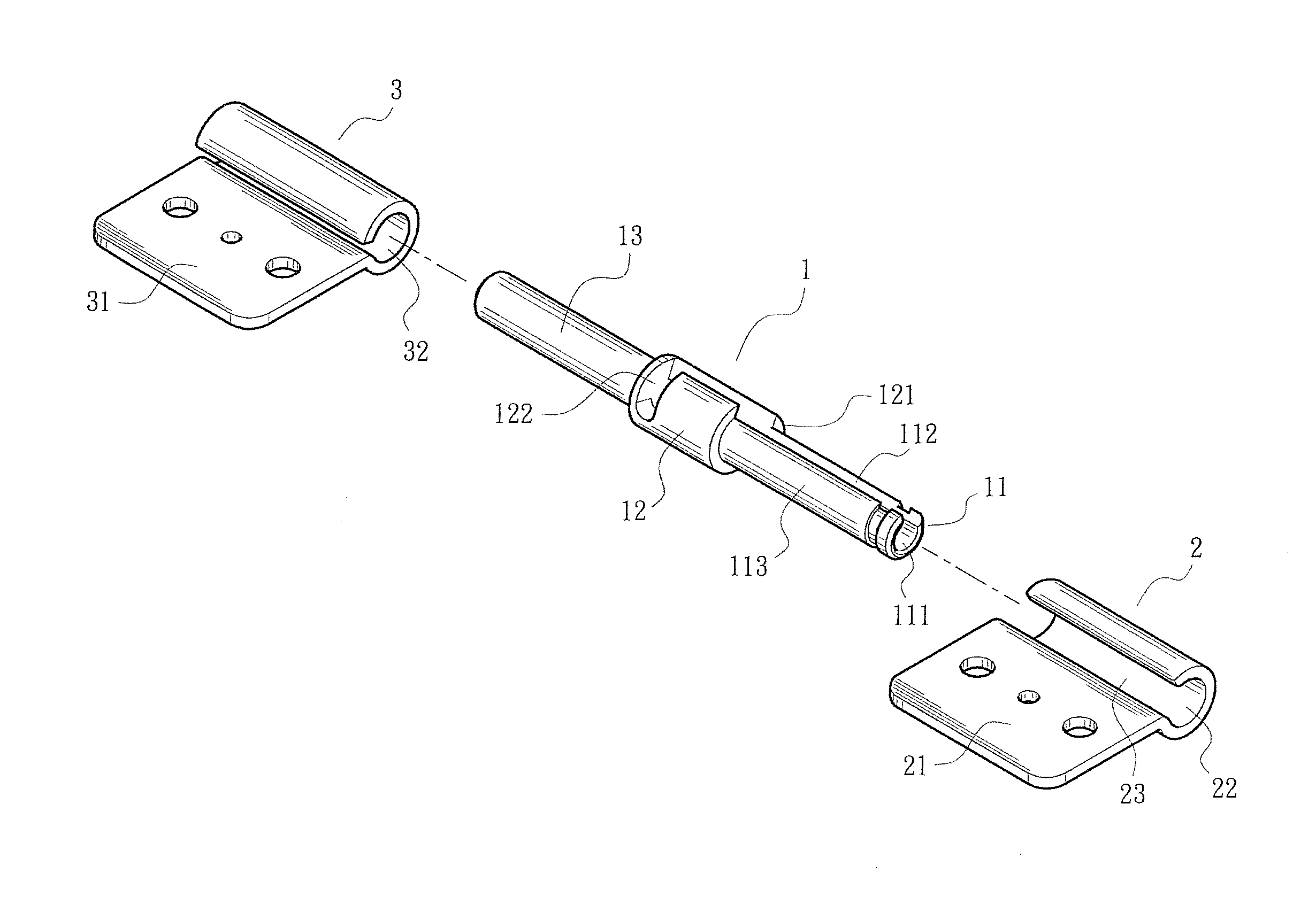
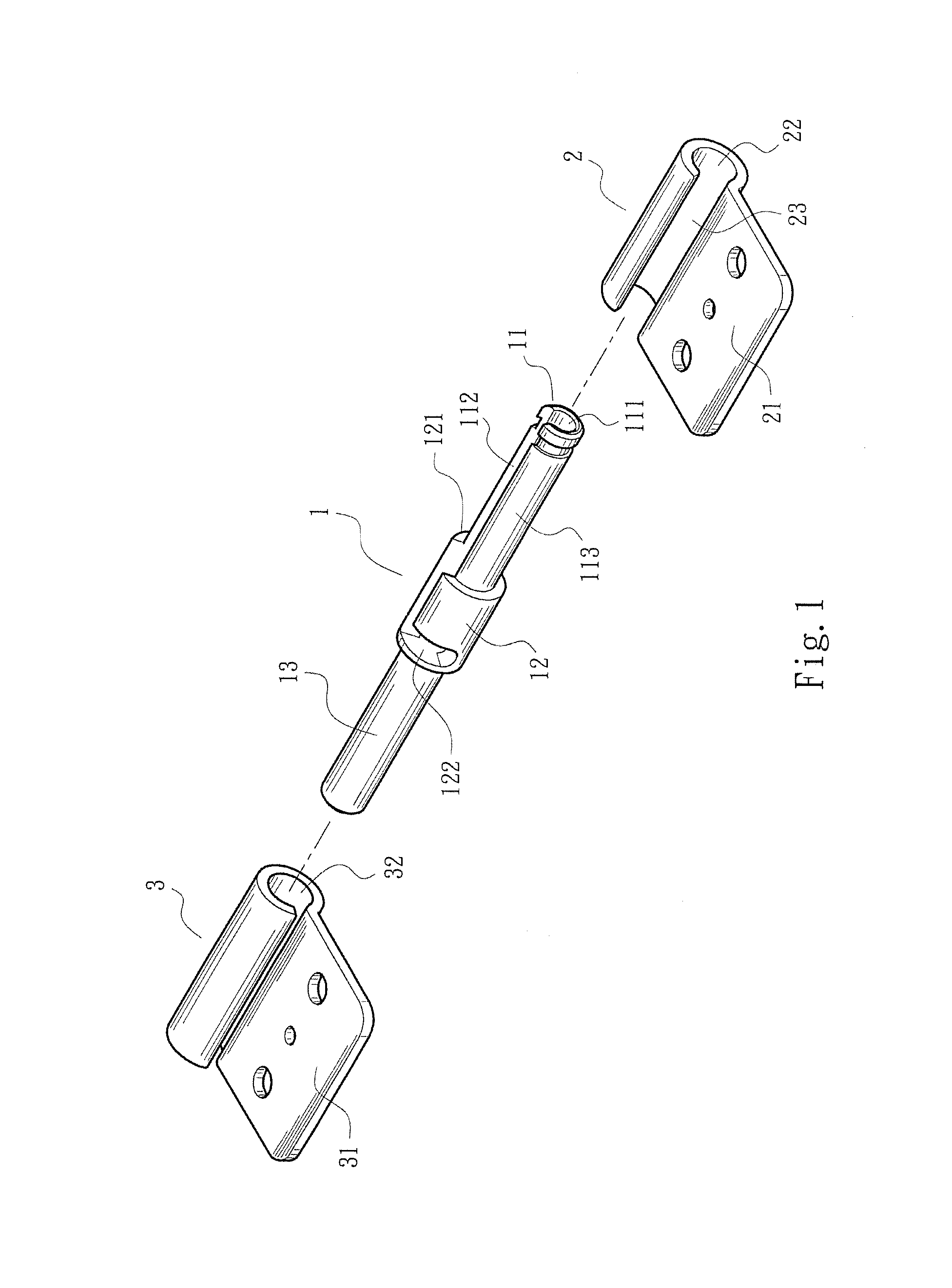
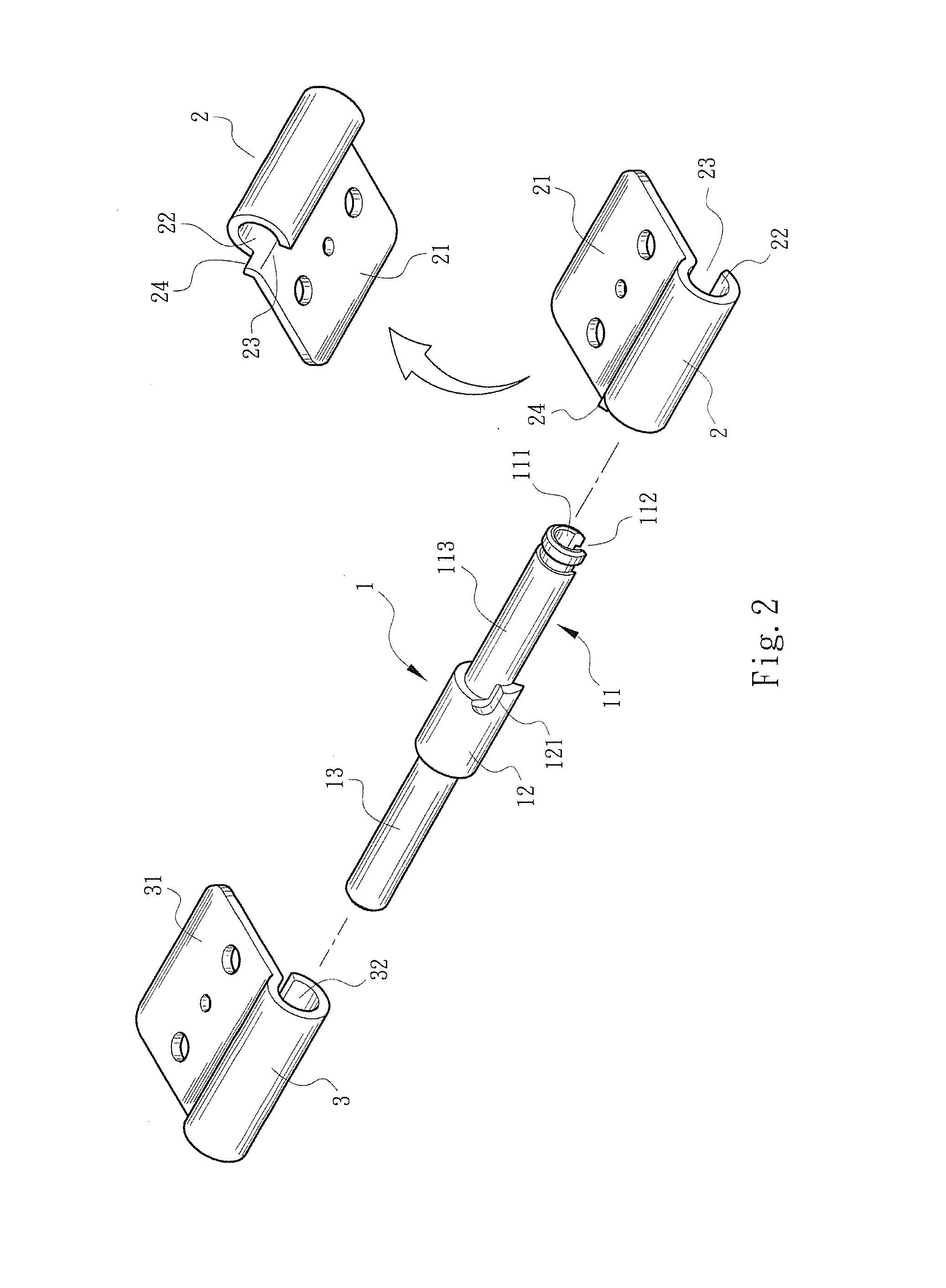
[0030]Please refer to FIGS. 1 and 2. The rotary shaft wire passage structure of the present invention includes a pivot pin 1 and a pivot seat 2. The pivot pin 1 has a pivoted section 11 and an annular raised section 12 disposed at one end of the pivoted section 11. A center of the pivoted section 11 is formed with an axial through hole 111 extending to the annular raised section 12. The through hole 111 is fully in communication with outer side via a split 112. The annular raised section 12 is formed with a transversely extending cut 122 in communication with the split 112. An outer circumference of the pivoted section 11 except the split 112 forms a pivoted surface 113. One side of the annular raised section 12, which side is adjacent to the pivoted section 11, is formed with a protruding stop section 121. The pivot seat 2 has a fixing section 21 and a shaft hole 22 in which the pivoted section 11 can be tightly fitted. One side of the shaft hole 22 is formed with a fissure 23 in c...


PUM


Abstract

A rotary shaft wire passage structure includes a pivot pin and a pivot seat respectively fixedly connected with a pivotal rotary member and a relative pivotal rotary member. The pivot pin has a pivoted section and an annular raised section disposed at one end thereof. The pivoted section is formed with an axial through hole in full communication with outer side via a split. The pivot seat has a shaft hole in which the pivoted section is fitted. One side of the shaft hole is formed with a fissure in communication with the outer side. The fissure is adjustable to a position where the fissure is aligned with the split for placing a wire into the through hole. When the relative pivotal rotary member is pivotally rotated to a working position by a certain angle, the fissure is misaligned from the split to prevent the wire from slipping out.

Description

BACKGROUND OF THE INVENTION[0001]1. Field of the Invention[0002]The present invention relates generally to an improved rotary shaft wire passage structure, and more particularly to a rotary shaft structure, which is easy to assemble and able to provide full protection for the wire without affecting operation of the product.[0003]2. Description of the Related Art[0004]A conventional rotary shaft wire passage structure generally includes a rotary shaft pivotally connected between a pivotal rotary member (such as a screen) and a relative pivotal rotary member (such as a main body). The rotary shaft is formed with a central through hole having two openings at two ends of the rotary shaft respectively. A wire can be conducted from the relative pivotal rotary member (the main body) through the rotary shaft into the pivotal rotary member (the screen). There is a trend to miniaturize and sophisticate the electronic product. Therefore, the relative pivotal rotary member (the main body) and t...

Claims


Application Information

Patent Timeline
Patent Type & Authority Applications(United States)
IPC IPC(8): F16L5/00E05D5/10
CPCG06F1/1683G06F1/1681
Inventor HSU, AN SZU
Owner FIRST DOME
Learn More