
Wheel hub structure of a bicycle

Inactive Publication Date: 2014-01-23
CHANG BIN
View PDF0 Cites 1 Cited by
  • Summary
  • Abstract
  • Description
  • Claims
  • Application Information

AI Technical Summary

Benefits of technology

The present invention provides an improved driving structure for bicycles. The patent describes two ways to increase the length of the wheel hub and balance the gravity center of the wheel hub. This results in a more stable and balanced bicycle ride.

Problems solved by technology

Therefore, it is not only inconvenient for the user to replace the ratchet base 5a with the further ratchet base 5b, but also spending much money on the further ratchet base 5b.

Method used


Image

  • Wheel hub structure of a bicycle
  • Wheel hub structure of a bicycle
  • Wheel hub structure of a bicycle

Examples


first embodiment

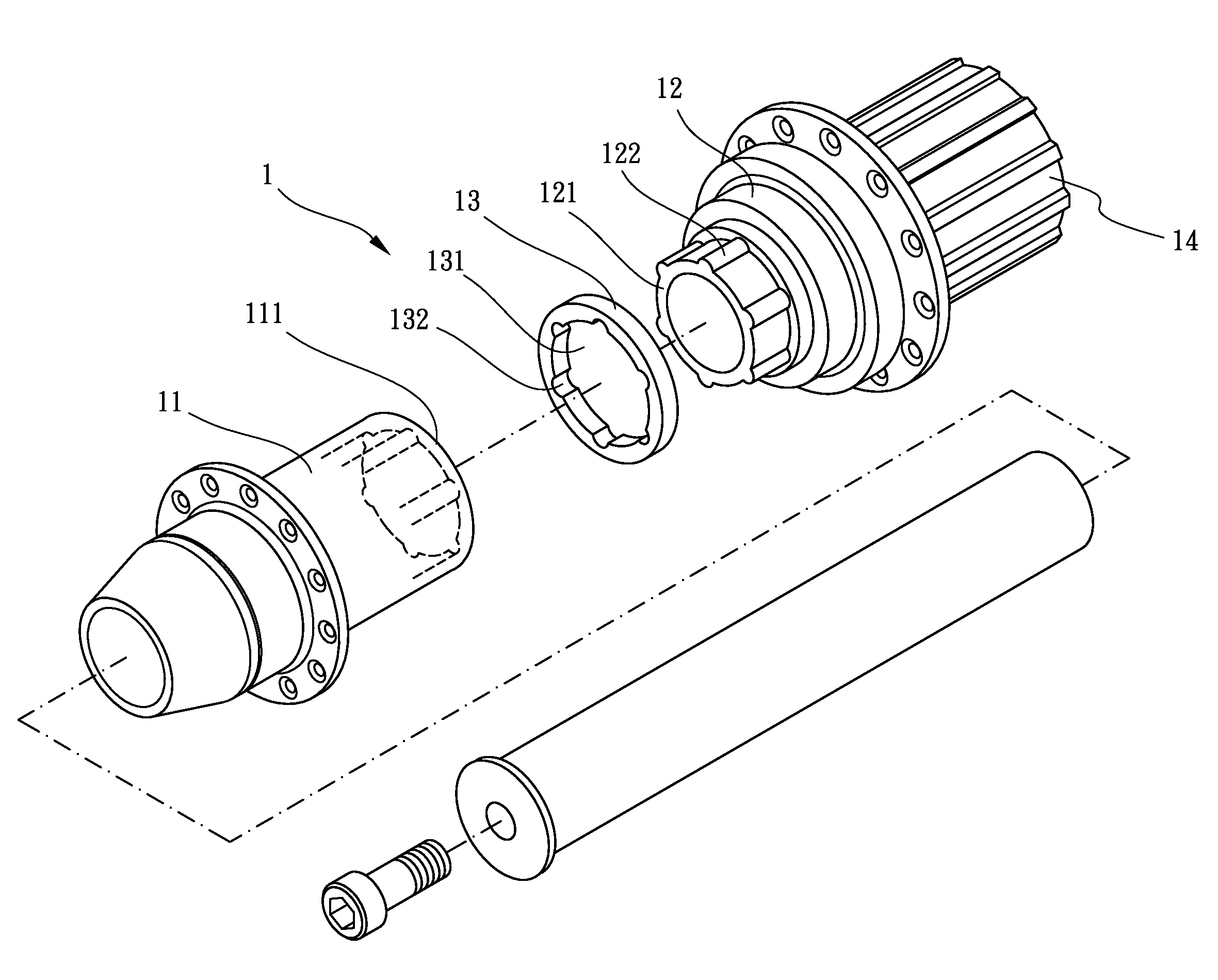
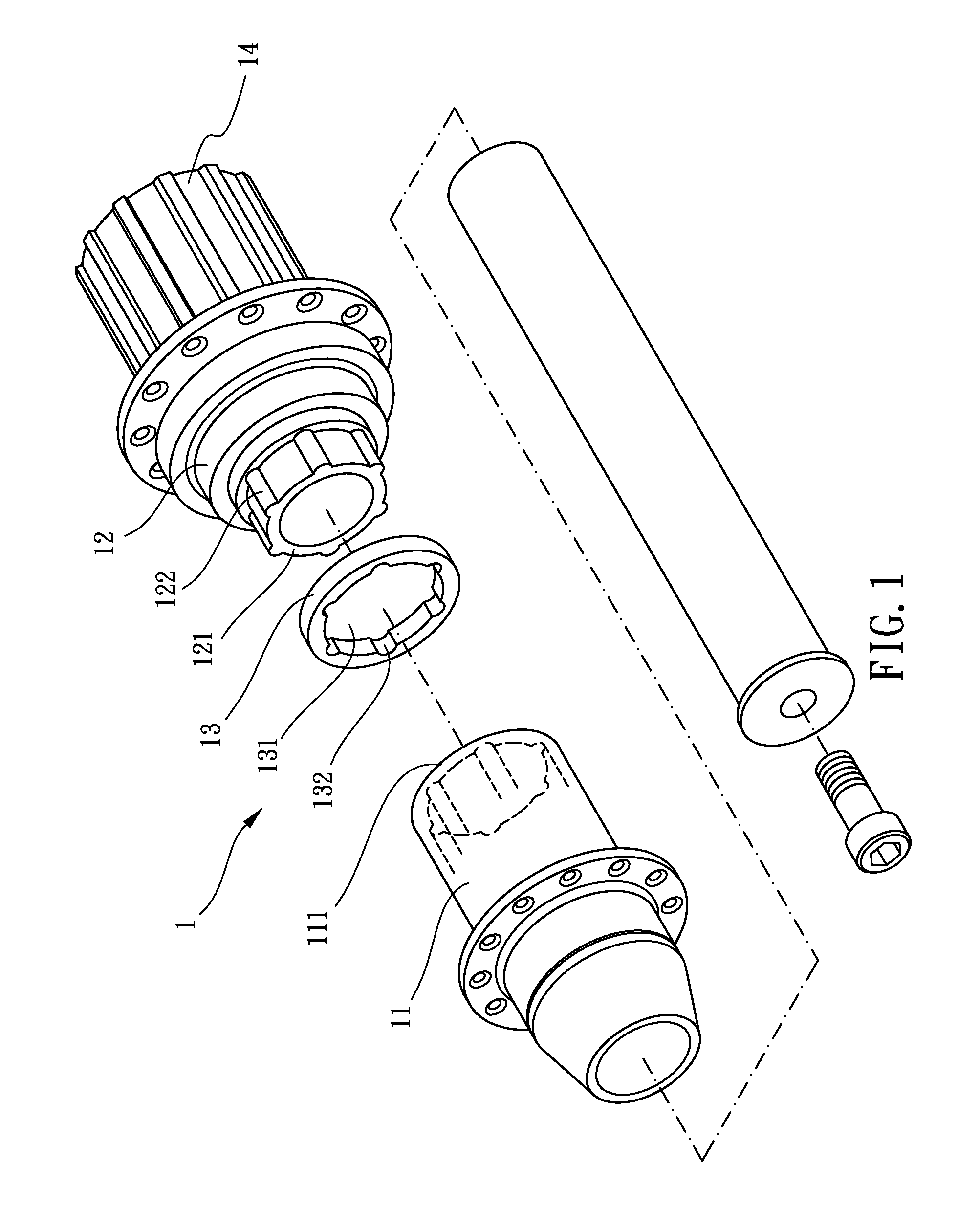
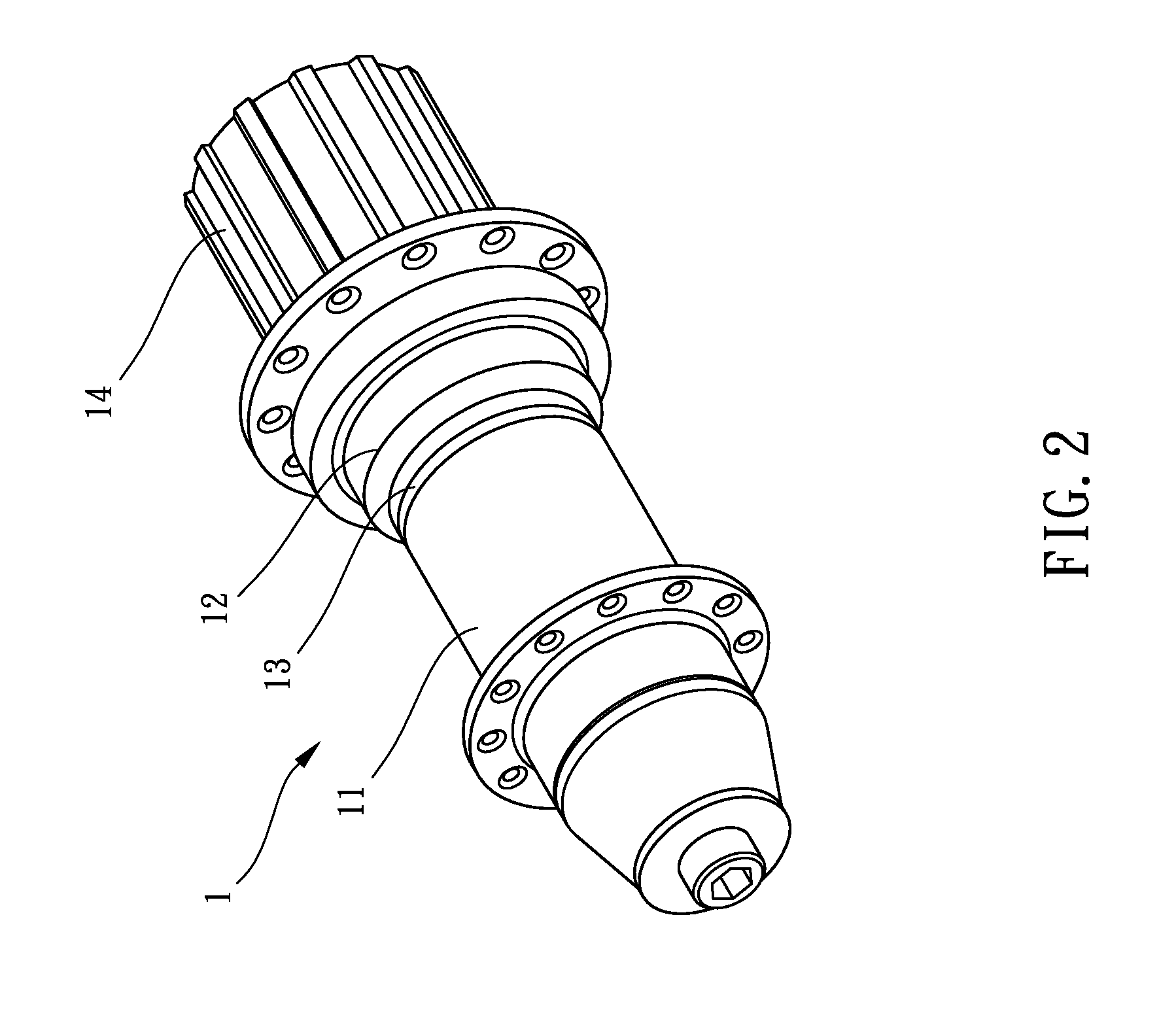
[0028]Referring to FIGS. 1-4, that shows a wheel hub structure of a bicycle in accordance with the present invention. The wheel hub structure of a bicycle in accordance with the present invention comprises a wheel hub 1.

[0029]The wheel hub 1 has a first hub body 11, a second hub body 12, a shrink ring 13, a ratchet base 14 with a freewheel set 2a (in the first embodiment, the freewheel set 2a has ten freewheels as shown in FIG. 4). The first hub body 11 has a first connecting portion 111 defined at one end thereof. The second hub body 12 has a second connecting portion 121 defined at one end thereof. The second connecting portion 121 of the second hub body 12 is corresponding to the first connecting portion 111 of the first hub body 11. The shrink ring 13 sleeves onto the second connecting portion 121 of the second hub body 12. The ratchet base 14 is mounted at another end of the second hub body 12.

[0030]Under this arrangement, the shrink ring 13 sleeves onto the second connecting p...

second embodiment

[0035]Referring to FIGS. 5-8, that shows the present invention. A wheel hub structure of a bicycle in accordance with the present invention comprises a wheel hub 1′.

[0036]The wheel hub 1′ has a first hub body 11′, a second hub body 12′, a shrink ring 13′ and a ratchet base 14′ with a freewheel set 2b (in the second embodiment, the freewheel set 2b has eleven freewheels as shown in FIG. 8). The first hub body 11′ is assembled to one end of the second hub body 12′. The second hub body 12′ has a receiving portion 122′ defined at another end thereof. The ratchet base 14′ has an inserting portion 141′ defined at one end thereof. The ratchet base 14′ has a plurality of insertion grooves 142′ defined around an outer periphery thereof. The inserting portion 141′ of the ratchet base 14′ is inserted into the receiving portion 122′ of the second hub body 12′. The shrink ring 13′ has a plurality of axial grooves 131′. Each axial groove 131′ is corresponding to each corresponding insertion groov...


PUM


Abstract

A wheel hub structure of a bicycle includes a wheel hub having a first hub body, a second hub body, a shrink ring, and a ratchet base. The shrink ring could be assembled between the first hub body and the second hub body or between the second hub body and ratchet base. Therefore, the length of the wheel hub or the ratchet base could be increased.

Description

BACKGROUND OF THE INVENTION[0001]1. Field of the Invention[0002]The present invention relates to a wheel hub and more particularly to a wheel hub structure of a bicycle.[0003]2. Description of Related Art[0004]Bicycle activity is more and more popular in these days because bicycle activity is eco-friendly, convenient and entertaining. Many enterprises encourage their employees to go to work by bicycles instead of driving vehicles today. Many people also go shopping or go traveling by bicycles during their leisure time. Because a wheel hub of a bicycle is very important for the comfort of riding, the improvement of the wheel hub structure is continuously progressed.[0005]The sequence for driving a bicycle is that when a rider treads on the pedals of a bicycle, one of chain wheels with different sizes will drive one of freewheels with different sizes via a drive chain, so that the wheel hub is driven by the freewheel to drive the bicycle move forward. In addition, a derailleur system ...

Claims


Application Information

Patent Timeline
IPC IPC(8): B60B27/00
CPCB60B27/00B60B27/023B60B27/047
Inventor CHANG, BIN
Owner CHANG BIN
Learn More