Electric device of passenger car split sliding plug door

A technology for electric devices and passenger cars, which is applied to the suspension devices of wing sashes, door/window accessories, power control mechanisms, etc. Noise, reduce dead weight, optimize the effect of drive structure

Pending Publication Date: 2020-11-10
IVY MACHINERY NANJING +1
View PDF1 Cites 0 Cited by
  • Summary
  • Abstract
  • Description
  • Claims
  • Application Information

AI Technical Summary

Problems solved by technology

However, the structure of this patent is complicated, and the structure of double transmission screw and double guide rod is adopted, which takes up a lot of space and makes a lot of noise in the initial state of closing the door.

Method used


Image

  • Electric device of passenger car split sliding plug door
  • Electric device of passenger car split sliding plug door
  • Electric device of passenger car split sliding plug door

Examples


Embodiment 1

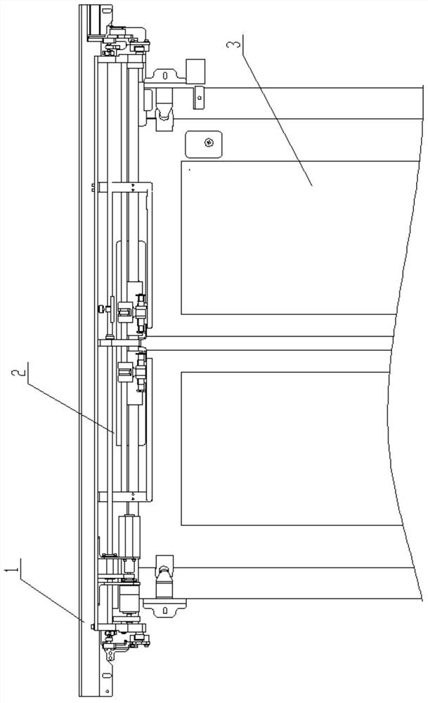
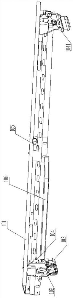
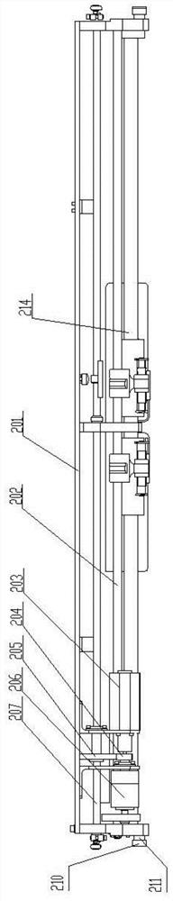
[0024] See attached figure 1 , attached figure 2 , attached image 3 As shown, the passenger car side-by-side plug-and-pull door electric device of the present invention includes a track box 1 fixed with the passenger car body and a plug-in driving trolley 2 installed in the track box, and the left and right side plate bottoms of the track box are respectively provided with Sierra guide rail 103, the middle part of track box 1 is provided with a guide slideway 106 that controls passenger car door 3 action sequences, (according to passenger car door closing action sequence) guide slideway 106 is set by moving from left to right. The car body of Sierra driven trolley 2 is made of left and right two car body end plates, a top beam, and a bottom guide bar 214. The bottom guide bar 214 is arranged at the front part of the car body, and its two ends are respectively fixedly connected with the lower parts of the two left and right car body end plates. A transmission screw 202 is a...

Embodiment 2

[0034] This embodiment is an improvement made on the basis of Embodiment 1. For the same content in this embodiment as Embodiment 1, please refer to the content disclosed in Embodiment 1 for understanding, and no repeated description is made here; the disclosure in Embodiment 1 The content should also be taken as the content disclosed in this embodiment.

[0035] See attached figure 1 , attached figure 2 , in this embodiment, in order to reduce the self-weight of the Sierra-driven trolley and prevent the left and right from getting stuck in the movement of the left and right masts, a load-carrying suspension rail 105 is arranged in the middle of the track box 1, and a suspension slider is arranged on the top of the Sierra-driven trolley. The suspension slider is matched and installed together with the load-bearing suspension rail 105 , and the load-bearing suspension rail 105 is arranged parallel to the pull guide rail 103 .


PUM


Abstract

The invention relates to an electric device of a passenger car split sliding plug door. The electric device comprises a rail box fixed to a passenger car body and a sliding plug driving trolley installed in the rail box, the rail box is provided with two sliding plug guide rails, and a guide sliding way is arranged in the middle of the rail box; a trolley body of the sliding plug driving trolley is composed of a left trolley body end plate, a right trolley body end plate, a top cross beam and a bottom guide bar, a transmission lead screw is arranged above the bottom guide bar, a left-hand thread section is arranged at the left portion of the transmission lead screw, a right-hand thread section is arranged at the right portion of the transmission lead screw, a left-hand nut assembly is installed at the left-hand thread section, and a right-hand nut assembly is installed at the right-hand thread section; and the left portion of the bottom guide bar is sleeved with a left door carrying frame, and the right portion of the bottom guide bar is sleeved with a right door carrying frame. According to the electric device, the size and the weight of the sliding plug driving trolley are optimized, the axial positions of the left door carrying frame and the right door carrying frame can be accurately adjusted, and impact and noise generated in the running process of the sliding plug drivingtrolley are eliminated.

Description

Technical field: [0001] The invention relates to the technical field of passenger car sliding doors, in particular to an electric device for side-by-side sliding doors of passenger cars. Background technique: [0002] With the development of rail transit, automatic doors with structures such as sliding doors, external doors, and built-in doors are widely used in rail transit passenger cars and platforms. Chinese patent 201220298714.1 discloses an electric device for a passenger car plug door, including a rail box and a plug-in driving trolley; two plug-in guide rails are arranged oppositely at the lower part of the rail box, and a guiding slide rail is arranged in the middle of the rail box; the bottom of the plug-in driving trolley is arranged Two wheels, a Sierra driving shaft is arranged on the upper part of the car body, a fan-shaped Sierra gear is arranged on the left side of the Sierra driving shaft, a left crank and a left connecting rod are installed on the left end ...

Claims


Application Information

Patent Timeline
Patent Type & Authority Applications(China)
IPC IPC(8): E05F15/652E05F5/06E05D15/06
CPCE05D15/0604E05D15/0652E05F5/06E05Y2900/51E05Y2900/531E05F15/652
Inventor 童海波田兴华
Owner IVY MACHINERY NANJING
Why Eureka
Try Eureka