Phase interpolating apparatus and method

a phase interpolation and phase technology, applied in pulse generators, pulse manipulation, pulse techniques, etc., can solve problems such as unrecoverable errors, waveform becomes incorrect, interpolated clock signal display un-normal surge or decay, etc., to achieve the effect of maintaining processing speed

Active Publication Date: 2014-01-23
MEDIATEK INC
View PDF3 Cites 0 Cited by
  • Summary
  • Abstract
  • Description
  • Claims
  • Application Information

AI Technical Summary

Benefits of technology

[0012]According to the described embodiments, switching input signals in advance according to a prediction result of the next phase to be interpolated is embodied to prevent voltage pulse problems experienced in the prior art and to maintain processing speed. Also, sharing multiplexers and phase interpolating modules enable circuit area to be saved accordingly.

Problems solved by technology

However, the voltage pulse P which appeared at the timing point T2 cause un-recoverable errors.
Such errors make the interpolated clock signal display un-normal surge or decays, so the waveform becomes incorrect.
However, the processing speed is slower in this configuration, and more complicated logic circuits are needed to control the switch and the interpolation separately.

Method used


Image

  • Phase interpolating apparatus and method
  • Phase interpolating apparatus and method
  • Phase interpolating apparatus and method

Examples


Embodiment Construction

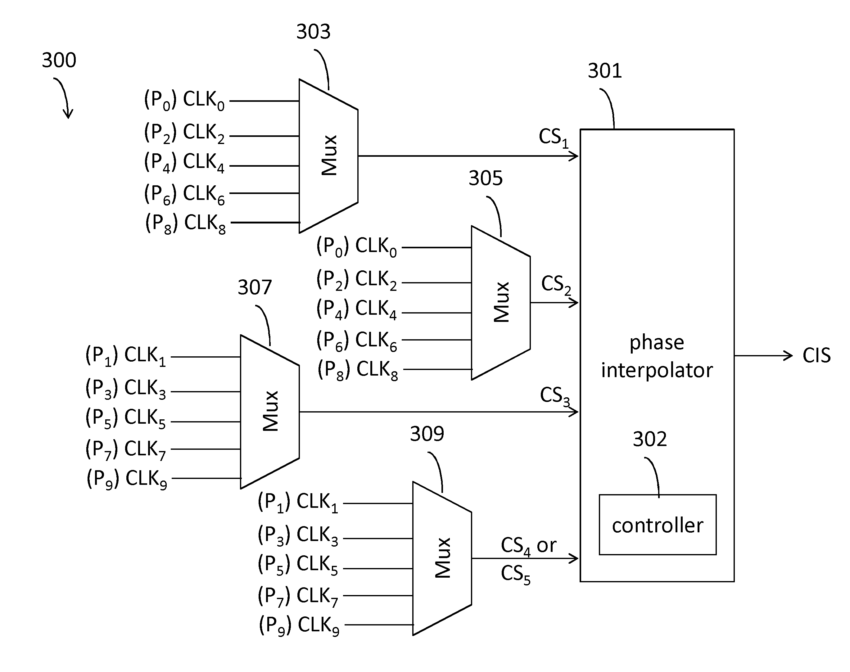
[0022]Please refer to FIG. 3, which shows a block diagram of a phase interpolating apparatus 300 in accordance with an embodiment of the present invention. As shown in FIG. 3, clock signals CLK0, CLK2, CLK4, CLK6, and CLK8 have even phases P0, P2, P4, P6, and P8, respectively. Similarly, clock signals CLK1, CLK3, CLK5, CLK7, and CLK9 have odd phases P1, P3, P5, P7, and P9, respectively. The phase interpolating apparatus 300 comprises a phase interpolator 301 and multiplexers 303, 305, 307, and 309. The multiplexers 303 and 305 receive clock signals CLK0, CLK2, CLK4, CLK6, and CLK8 and output a first clock signal CS1 and a second clock signal CS2 to the phase interpolator 301, respectively. The multiplexer 307 receives clock signals CLK1, CLK3, CLK5, CLK7, and CLK9 and outputs a third clock signal CS3 to the phase interpolator 301. The multiplexer 309 receives clock signals CLK1, CLK3, CLK5, CLK7, and CLK9 and outputs a fourth clock signal CS4 or a fifth clock signal CS5 to the phase...


PUM


Abstract

The present invention discloses a phase interpolating apparatus comprising: a first signal generation circuit, configured for generating a first signal having a first phase; an optional second signal generation circuit, configured for generating a second signal having the first phase; a third signal generation circuit, configured for generating a third signal having a second phase; a fourth/fifth signal generation circuit, configured for generating a fourth signal having a third phase when operating in a first mode and for generating a fifth signal having the second phase instead of the fourth signal when operating in a second mode; and a phase interpolator, configured for generating an interpolated signal without utilizing the fourth signal when operating in the first mode and for generating the interpolated signal according to the first signal, the third signal, and the fifth signal when operating in the second mode.

Description

CROSS REFERENCE TO RELATED APPLICATIONS[0001]This application claims priority under 35 U.S.C 119 to Taiwan patent application, TW101126458, filed on Jul. 23, 2012, the disclosure of which is incorporated herein by reference.BACKGROUND OF THE INVENTION[0002]1. Field of the Invention[0003]The present invention relates to a phase interpolating apparatus and associated phase interpolating method, and more particularly, to a phase interpolating apparatus and method capable of predicting interpolation and switching phase to be interpolated in advanced.[0004]2. Description of the Prior Art[0005]A phase interpolating apparatus is widely used in modern electronics because it is used to generate multiple clock signals having different phases based on few clock signals. Please refer to FIG. 1, which illustrates a block diagram of a phase interpolating apparatus 100 in the prior art. As shown in FIG. 1, the phase interpolating apparatus 100 in the prior art comprises a phase interpolator 101 an...

Claims


Application Information

Patent Timeline
Patent Type & Authority Applications(United States)
IPC IPC(8): H03K3/01
CPCH03K3/01H03K5/135H03K2005/00052
Inventor WENG, MENG-TSE
Owner MEDIATEK INC
Why Eureka
Try Eureka