Fast brillouin optical time domain analysis for dynamic sensing

a dynamic sensing and optical time domain technology, applied in the field of dynamic brillouin sensing, can solve problems such as fair slow procedur

Active Publication Date: 2014-01-23
RAMOT AT TEL AVIV UNIV LTD
View PDF8 Cites 15 Cited by
  • Summary
  • Abstract
  • Description
  • Claims
  • Application Information

AI Technical Summary

Benefits of technology

[0005]According to one aspect of the invention, there is provided a method for conducting fast Brillouin optical time domain analysis for dynamic sensing of optical fibers. The method includes the following stages: injecting a pump pulse signal into a first end of an optical fiber; injecting a probe signal into a second end of an optical fiber, wherein the probe and the pump pulse signals exhibit a frequency difference therebetween that is appropriate for an occurrence of a Brillouin effect, in which the probe signal is amplified by a Brillouin effect, to yield a probe wave whose gain corresponds to matching between the fiber physical properties and the pump-probe waves frequency difference, at each point along the fiber, at any point of time; alternating the frequency of either the probe or the pulse signals, so as the alternated signal exhibits a series of signal sections, each signal section having a predefined common duration and a different frequency; measuring the Brillouin probe gain for each one of the alternating frequencies; and extracting physical properties of the optical fiber throughout its length at sample points associated with the sampled time and the frequencies, based on the measured Brillouin probe gain, to yield a dynamic analysis of the physical properties of the optical fiber.

Problems solved by technology

In order achieve high strain / temperature resolution over a wide dynamic range of these two measurands, the scanned frequency range must be wide (>100 MHz) and of high granularity, resulting in a fairly slow procedure, that often requires multiple scanning to reduce noise.

Method used


Image

  • Fast brillouin optical time domain analysis for dynamic sensing
  • Fast brillouin optical time domain analysis for dynamic sensing
  • Fast brillouin optical time domain analysis for dynamic sensing

Examples


Embodiment Construction

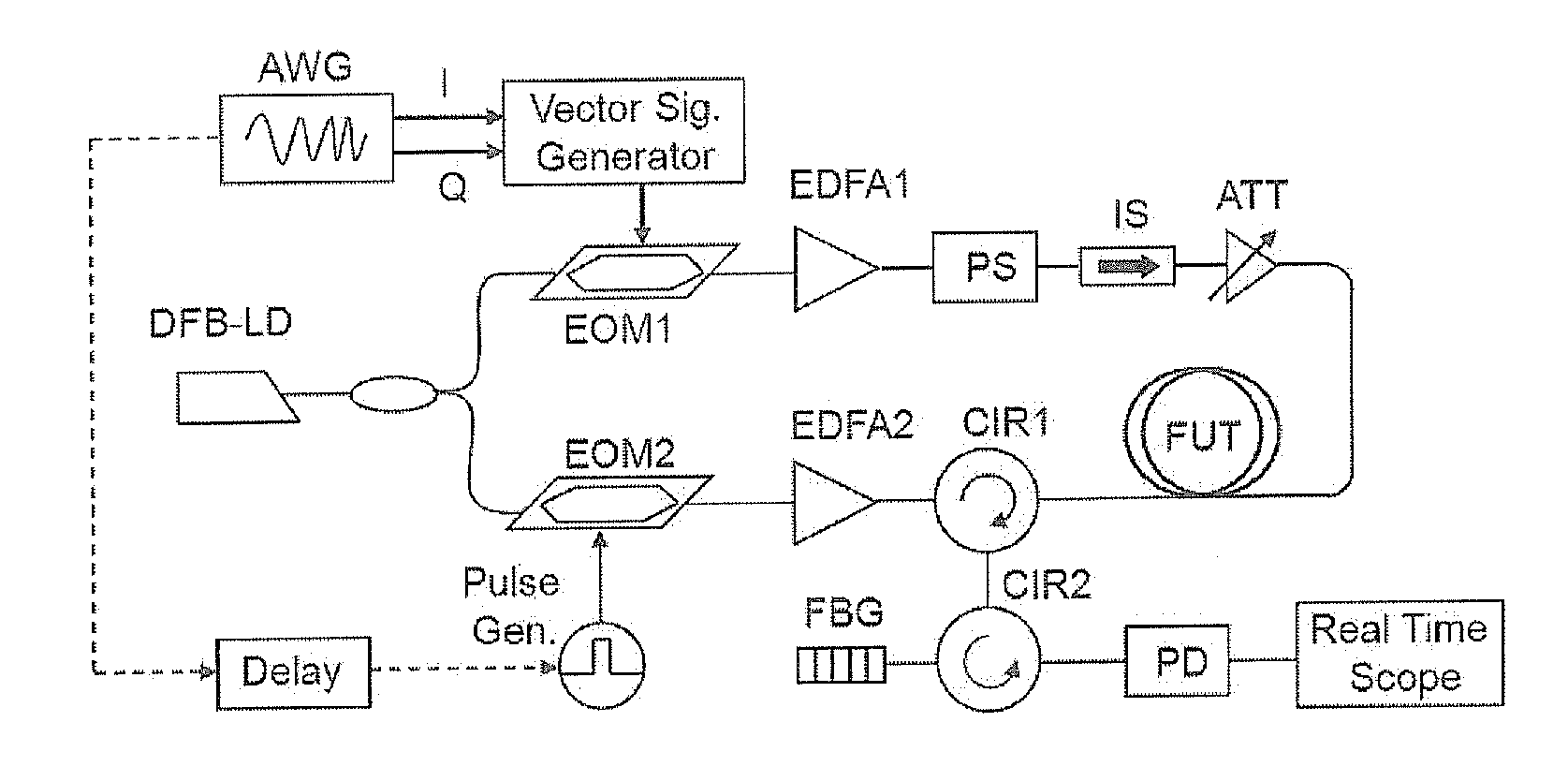
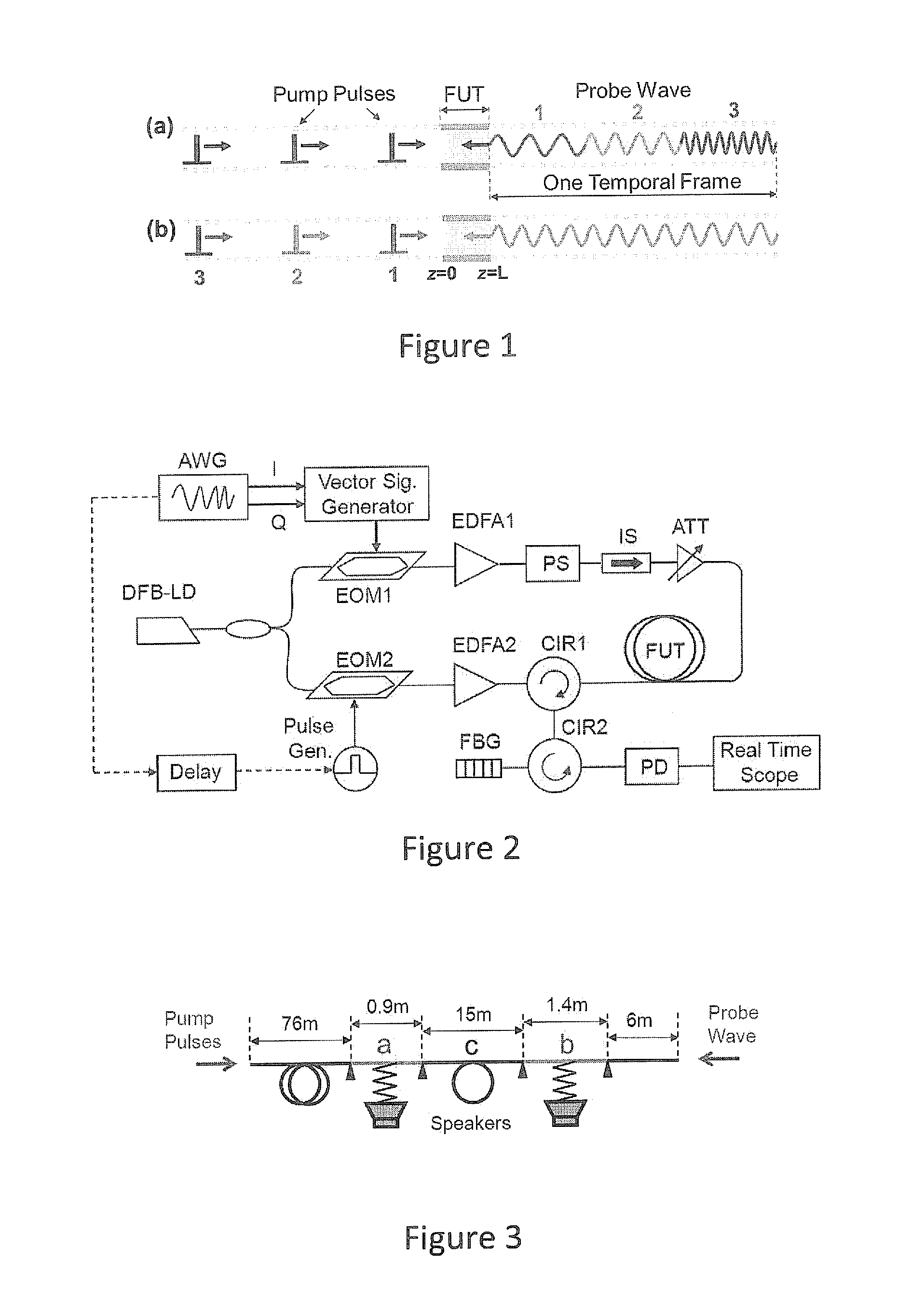
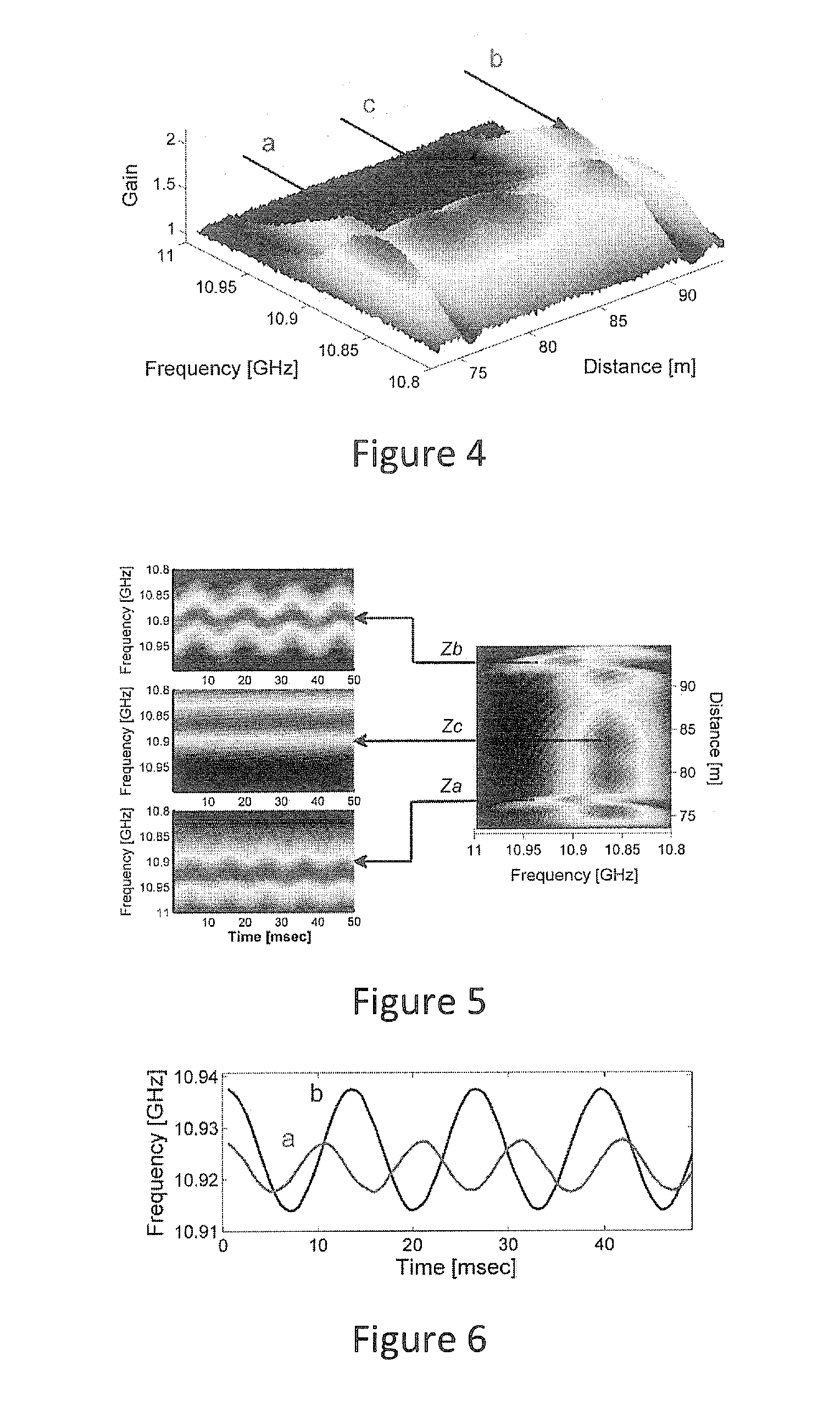
[0014]The present invention, in embodiments thereof, suggests generating both the pump and probe waves from the same highly coherent laser by using an electro-optic modulator to create a frequency difference between the pump (directly derived from the laser) and probe (down shifted in frequency from that of the laser by a controllable difference on the order of the BFS˜11 GHz). The modulator is normally driven by a relatively slowly sweeping YIG- or VCO-based electronic synthesizer, whose frequency is scanned at a rate on the order of 1 ms per frequency step (or slower), to cover the frequency span of interest (100's of MHz). Instead, we propose the use of an arbitrary waveform generator (AWG). While the pump pulse frequency is maintained at a fixed value, the probe frequency can be changed every Tround—trip=1 μs (for a 100 m long fiber).

[0015]This very fast change may be obtained by first writing into the deep memory of the AWG a numerical description of 1 μs long sine wave of the ...


PUM


Abstract

A method for conducting fast Brillouin optical time domain analysis for dynamic sensing of optical fibers is provided herein. The method includes the following stages: injecting a pump pulse signal into a first end of an optical fiber and a probe signal into a second end of the optical fiber, wherein the probe and the pump pulse signals exhibit a frequency difference between them that is appropriate for an occurrence of a Brillouin effect; alternating the frequency of either the probe or the pulse signals, so as the alternated signal exhibits a series of signal sections, each signal section having a predefined common duration and a different frequency; measuring the Brillouin probe gain for each one of the alternating frequencies; and extracting physical properties of the optical fiber throughout its length at sample points associated with the sampled time and the frequencies, based on the measured Brillouin probe gain.

Description

CROSS REFERENCE TO RELATED APPLICATIONS[0001]The present patent application claims the benefit of U.S. Provisional Patent Application No. 61 / 674,006, filed on Jul. 20, 2012, which is incorporated herein by reference in its entirety.FIELD OF THE INVENTION[0002]The present invention relates to sensing Brillouin scattering in optical fibers, and more particularly, to a dynamic Brillouin sensing.BACKGROUND OF THE INVENTION[0003]The use of stimulated Brillouin scattering (SBS) for fiber optic strain and temperature distributed sensors is well known in the art. One of the most widely used approaches is the classical method of Brillouin optical time-domain analysis technique (BOTDA), where a pump pulse interacts with a counter propagating probe wave. Strain and temperature information is deduced from the local Brillouin gain spectrum (BGS), which is measured by scanning the optical frequency of the probe wave.[0004]In order achieve high strain / temperature resolution over a wide dynamic ran...

Claims


Application Information

Patent Timeline
Patent Type & Authority Applications(United States)
IPC IPC(8): G01M11/00
CPCG01M11/3172G01M11/39
Inventor PELED, YAIRTUR, MOSHE
Owner RAMOT AT TEL AVIV UNIV LTD
Why Eureka
Try Eureka