Method and apparatus for improved vision detector image capture and analysis

a technology of vision detector and image capture, applied in the field of automatic visual event detection, object detection and inspection, can solve the problem that frames cannot be captured as fast as possible all the time, and achieve the effect of predicting the time needed to inspect the object and increasing the frame ra

Inactive Publication Date: 2005-10-13
COGNEX TECH & INVESTMENT
View PDF40 Cites 65 Cited by
  • Summary
  • Abstract
  • Description
  • Claims
  • Application Information

AI Technical Summary

Benefits of technology

[0043] Another aspect of the invention includes a step or process that limits the number of frames to be captured and analyzed in an active state, so that the FIFO does not overflow and the time needed to inspect the object is predictable.
[0044] Yet another aspect of the invention...

Problems solved by technology

It is desirable to capture frames at the highest rate during active states, but frames cannot be...

Method used


Image

  • Method and apparatus for improved vision detector image capture and analysis
  • Method and apparatus for improved vision detector image capture and analysis
  • Method and apparatus for improved vision detector image capture and analysis

Examples


Embodiment Construction

Discussion of Prior Art

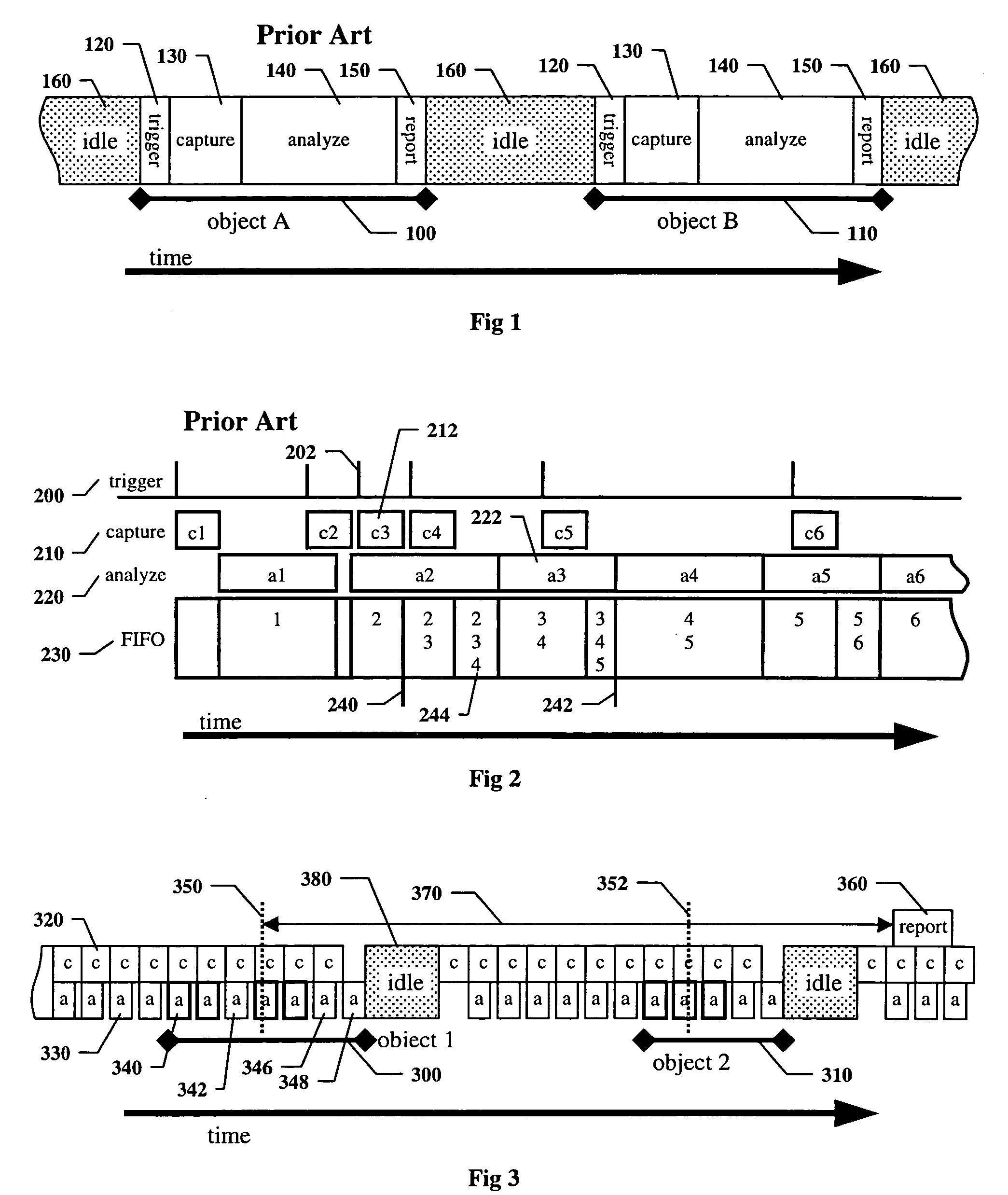
[0060]FIG. 1 shows a timeline that illustrates a typical operating cycle of a prior art machine vision system. Shown are the operating steps for two exemplary objects 100 and 110. The operating cycle contains four steps: trigger 120, image capture 130, analyze 140, and report 150. During the time between cycles 160, the vision system is idle. The timeline is not drawn to scale, and the amount of time taken by the indicated steps will vary significantly among applications.

[0061] The trigger 120 is some event external to the vision system, such as a signal from a photodetector, or a message from a Programmable Logic Controller (PLC), computer, or other piece of automation equipment.

[0062] The image capture step 130 starts by exposing a two-dimensional array of photosensitive elements, called pixels, for a brief period, called the integration or shutter time, to an image that has been focused on the array by a lens. Each pixel measures the intensity of light ...


PUM


Abstract

Disclosed are methods and apparatus for improvements to image capture and analysis for vision detectors. The improvements provide for asynchronous capture and analysis and allow high frame rates to be maintained when image analysis may under certain conditions comprise a significantly longer time interval than image capture. The improvements prevent memory buffer overflow and provide for short and predictable decision delays even though an arbitrary and potentially unlimited number of images are captured and analyzed for each object.

Description

RELATED APPLICATIONS [0001] This application is a continuation-in-part of the following co-pending U.S. patent applications: [0002] Ser. No. 10 / 865,155, entitled METHOD AND APPARATUS FOR VISUAL DETECTION AND INSPECTION OF OBJECTS, by William M. Silver, filed Jun. 9, 2004, the teachings of which are expressly incorporated herein by reference, and referred to herein as the “Vision Detector Method and Apparatus”; [0003] Ser. No. 10 / 979,535, entitled METHOD FOR SETTING PARAMETERS OF A VISION DETECTOR USING PRODUCTION LINE INFORMATION, by Brian Mirtich and William M. Silver, filed Nov. 2, 2004, a continuation-in-part of Vision Detector Method and Apparatus, the teachings of which are expressly incorporated herein by reference, and referred to herein as the “Parameter Setting Method and Apparatus”; and [0004] Ser. No. 11 / 059,512, entitled Method and Apparatus for Automatic Visual Detection, Recording, and Retrieval of Events, by William M. Silver and Brian S. Phillips, filed Feb. 16, 2005...

Claims


Application Information

Patent Timeline
IPC IPC(8): G06K9/00G06T7/00
CPCG06T7/0004G06T1/0007
Inventor PHILLIPS, BRIAN S.SILVER, WILLIAM M.MIRTICH, BRIAN V.
Owner COGNEX TECH & INVESTMENT
Why Eureka
Try Eureka