Disk drive suspension

Active Publication Date: 2014-01-23
NHK SPRING CO LTD
View PDF6 Cites 50 Cited by
  • Summary
  • Abstract
  • Description
  • Claims
  • Application Information

AI Technical Summary

Benefits of technology

[0013]Accordingly, the object of this invention is to provide a disk drive suspension configured so that electrical connection between electrodes of microactuator

Problems solved by technology

It is unnecessary, moreover, to dispose conducting members, such as lead

Method used


Image

  • Disk drive suspension
  • Disk drive suspension
  • Disk drive suspension

Examples


Embodiment Construction

[0037]A disk drive suspension according to a first embodiment of the present invention will now be described with reference to FIGS. 1 to 14.

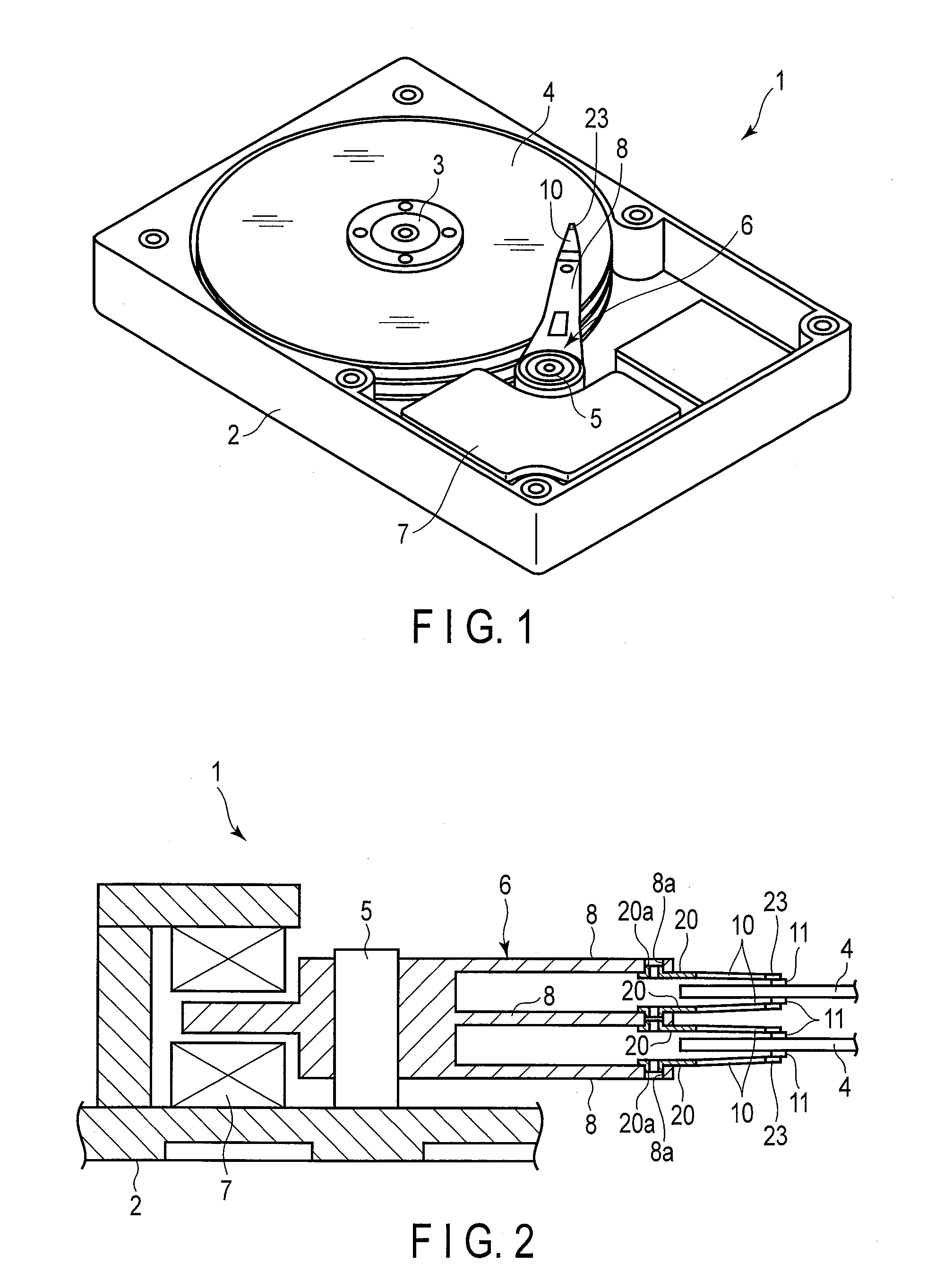
[0038]A disk drive (HDD) 1 shown in FIG. 1 comprises a case 2, disks 4 rotatable about a spindle 3, carriage 6 turnable about a pivot 5, positioning motor (voice coil motor) 7 for actuating the carriage 6, etc. The case 2 is sealed by a lid (not shown).

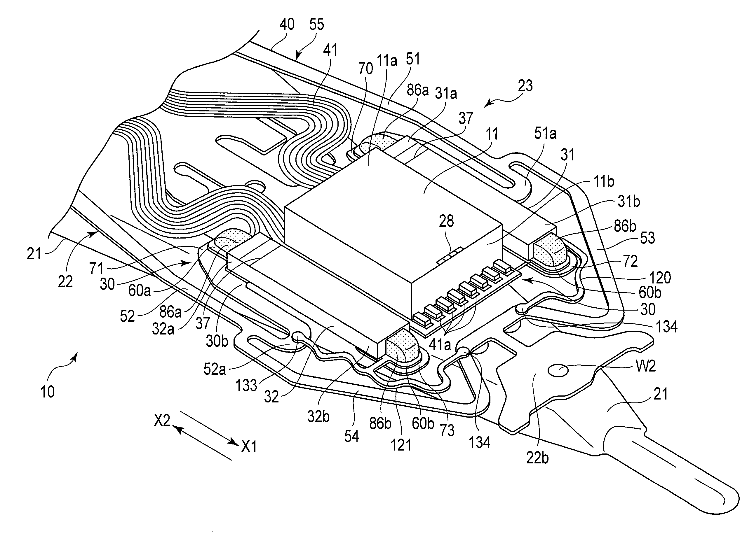
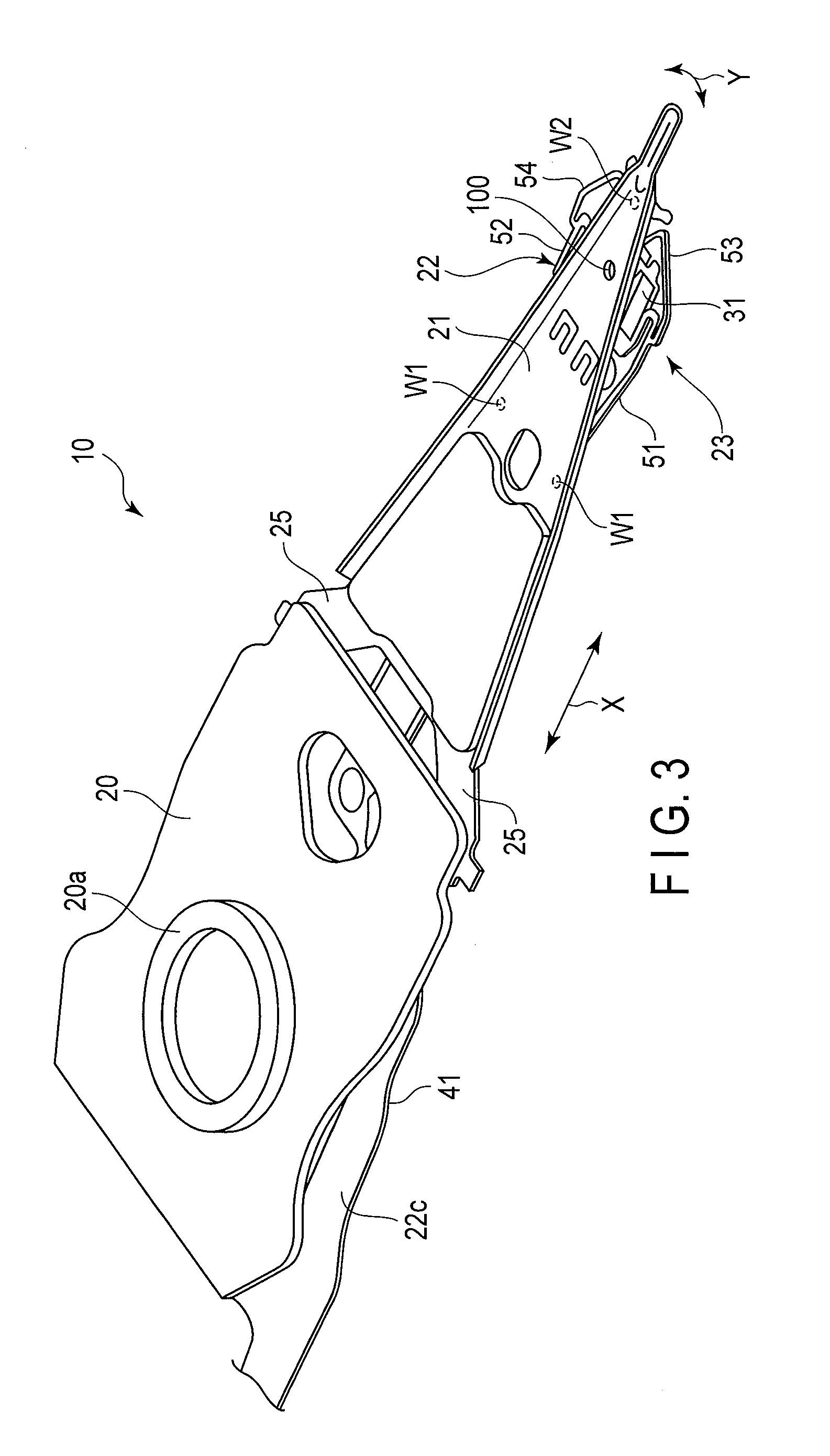
[0039]FIG. 2 is a sectional view schematically showing a part of the disk drive 1. As shown in FIGS. 1 and 2, the carriage 6 comprises arms (carriage arms) 8. A suspension 10 is mounted on the distal end portion of each arm 8. A slider, 11, which constitutes a magnetic head, is provided on the distal end portion of the suspension 10. In a state where each disk 4 rotates at high speed, an air bearing is formed between the disk and the slider 11 as air flows in between the disk 4 and slider 11. If the carriage 6 is turned by the positioning motor 7, the suspension 10 moves radially relative to the ...


PUM


Abstract

A microactuator element is disposed on a gimbal portion of a flexure. A first end of the element is secured to a first supporting portion by a first insulating adhesive. A second end is secured to a second supporting portion by a second insulating adhesive. A first conductor is disposed on the first supporting portion. A second conductor on the ground side is disposed on the second supporting portion. A first electrode is disposed on a first end of the element. A first electrically conductive paste is provided between the first electrode and the first conductor. A second electrode is disposed on a second end of the element. A second electrically conductive paste is provided between the second electrode and the second conductor.

Description

CROSS-REFERENCE TO RELATED APPLICATIONS[0001]This application is based upon and claims the benefit of priority from prior Japanese Patent Application No. 2012-160866, filed Jul. 19, 2012, the entire contents of which are incorporated herein by reference.BACKGROUND OF THE INVENTION[0002]1. Field of the Invention[0003]This invention relates to a disk drive suspension comprising a microactuator element of, for example, lead zirconate titanate (PZT).[0004]2. Description of the Related Art[0005]A hard disk drive (HDD) is used in an information processing apparatus, such as a personal computer. The HDD comprises a magnetic disk rotatable about a spindle, a carriage turnable about a pivot, etc. The carriage, which comprises an actuator arm, is configured to be turned transversely relative to tracks of the disk about the pivot by a positioning motor, such as a voice coil motor.[0006]A suspension is mounted on the actuator arm. The suspension comprises a load beam and flexure superposed ther...

Claims


Application Information

Patent Timeline
IPC IPC(8): G11B5/48
CPCG11B5/4813G11B5/483
Inventor HANYA, MASAOTAKIKAWA, KENICHIANDO, TOSHIKIINOUE, MASARU
Owner NHK SPRING CO LTD
Why Eureka
Try Eureka