
Finger-mountable ablation device

a technology of finger-mounted ablation and annular members, which is applied in the field of finger-mounted ablation devices, can solve the problems of limiting the amount of tactile sensory feedback received, disadvantageous to surgeons working, and often limited range of motion of electrosurgical instruments, so as to facilitate complex motions

Active Publication Date: 2014-01-23
TYCO HEALTHCARE GRP LP
View PDF2 Cites 78 Cited by
  • Summary
  • Abstract
  • Description
  • Claims
  • Application Information

AI Technical Summary

Benefits of technology

The present patent relates to an electrosurgical apparatus and methods for performing electrosurgical procedures, particularly endoscopic or endoluminal procedures. The invention provides a more dexterous electrosurgical instrument for facilitating complex motions during these procedures. The instrument has the capability to provide feedback to an operator on the performance of the electrosurgical device and the surrounding tissue, including temperature, mechanical strain, and other relevant characteristics. The invention also includes a sensor assembly that can detect changes in the transmission of light through an optical member and correlate it to a changed condition of the instrument, such as temperature or mechanical strain. The optical member can include a fiber Bragg grating and a plurality of segments with different refractive indices. The technical effects of the invention include improved dexterity, better feedback, and improved sealing capabilities during endoscopic or endoluminal procedures.

Problems solved by technology

However, electrosurgical instruments often have a limited range of motion, e.g., due to mechanical design constraints.
This limited range of motion may be disadvantageous to a surgeon working in an area that requires a complex series of movements.
Thus, the mechanical nature of some electrosurgical instruments may limit the amount of tactile sensory feedback received by the surgeon during a procedure.

Method used


Image

  • Finger-mountable ablation device
  • Finger-mountable ablation device
  • Finger-mountable ablation device

Examples


Embodiment Construction

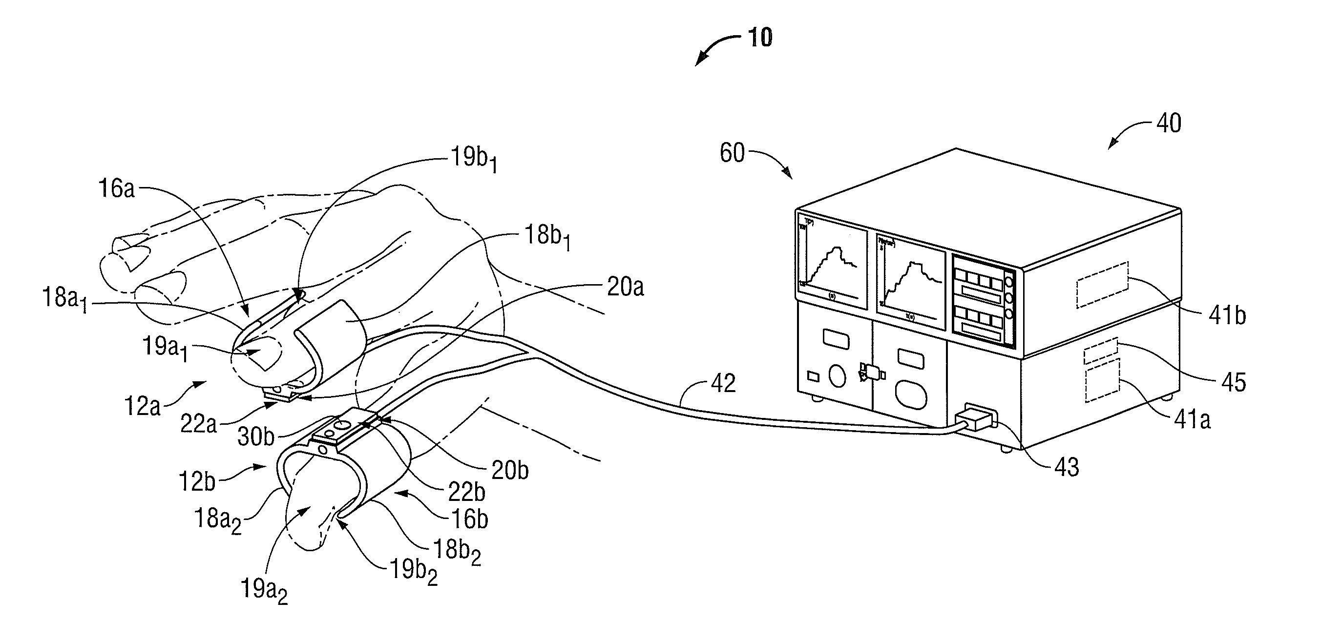
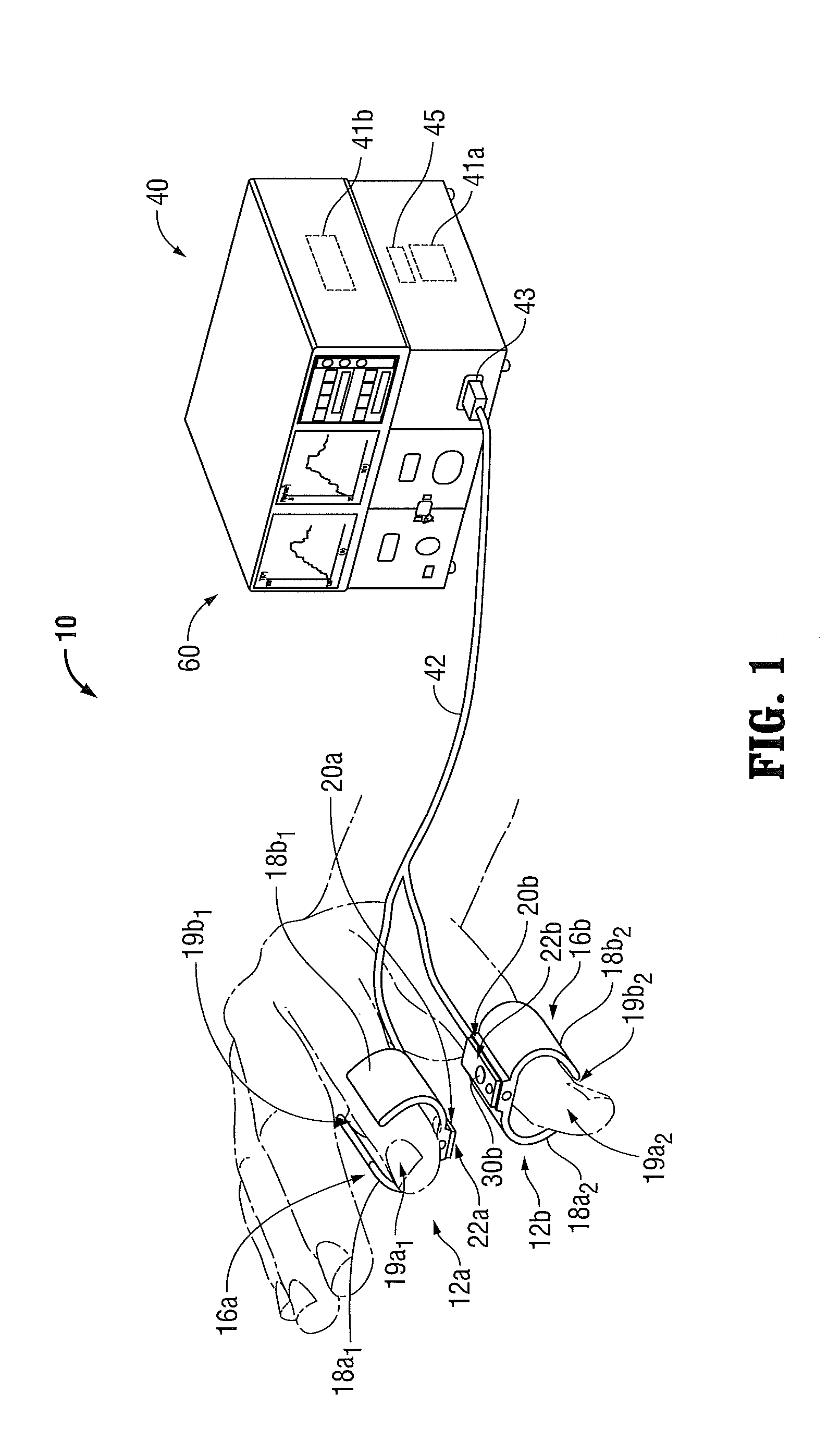
[0034]The present disclosure provides for a system and method for providing a variety of sensor feedback regarding operation of an electrosurgical device including a pair of finger-mountable annular members including, but not limited to, temperature of the finger-mountable annular members and the surrounding tissue, pressure exerted on the finger-mountable annular members, position and pressure of various mechanical components of the electrosurgical device, and identification information corresponding to the electrosurgical device. Although the feedback system according to present disclosure is described below with respect to a pair of finger-mountable annular members, the system may be utilized in a variety of surgical instruments, including but not limited to, open surgical forceps, tweezer-type devices, graspers, staplers, pencils, needles, and the like. Although this configuration is typically associated with instruments for use in laparoscopic or endoscopic surgical procedures,...


PUM


Abstract

A surgical device is disclosed, and includes a pair of finger-mountable annular members, each having an electrode disposed thereon. An optical member is disposed on at least one of the pair of finger-mountable annular members and has a first set of light transmitting properties corresponding to a first set of physical parameters of at least one of the finger-mountable annular members. At least one finger-mountable annular member is configured to transition to a second set of physical parameters being different from the first set of physical parameters. The optical member is configured to transition from a first set of light transmitting properties to a second set of light transmitting properties, the second set of light transmitting properties corresponding to the second set of physical parameters, the second set of light transmitting properties being different from the first set of light transmitting properties.

Description

CROSS REFERENCE TO RELATED APPLICATION[0001]The present application claims the benefit of and priority to U.S. Provisional Application Ser. No. 61 / 673,651, filed on Jul. 19, 2012, the entire contents of which are incorporated herein by reference.BACKGROUND[0002]1. Technical Field[0003]The present disclosure relates generally to an electrosurgical device, and more particularly to one or more finger-mountable annular members including an electrode for treating tissue and an optical fiber for the detection of the changing physical characteristics of the finger-mountable annular member.[0004]2. Background of Related Art[0005]Electrosurgical instruments are commonly used in open and minimally invasive surgical procedures. Because nerve and muscle stimulation cease at 100,000 cycles per second (100 kHz), electrosurgical procedures can be performed safely at radio frequencies (“RF”) above 100 kHz. At these frequencies, electrosurgical energy can pass through a patient with minimal neuromus...

Claims


Application Information

Patent Timeline
IPC IPC(8): A61B18/18
CPCA61B18/18A61B18/14A61B2017/00057A61B2017/00061A61B2017/00084A61B2017/00345A61B2017/00438A61B2018/00791A61B2562/0266A61B90/53A61B2090/064A61B2090/065A61B2034/2061A61B5/6826A61B2018/00589A61B2018/0063A61B2018/00648A61B2018/1253A61B2018/126A61B2018/1467A61B90/06G01D5/353
Inventor KERR, DUANE E.
Owner TYCO HEALTHCARE GRP LP
Features
  • Generate Ideas
  • Intellectual Property
  • Life Sciences
  • Materials
  • Tech Scout
  • Unparalleled Data Quality
  • Higher Quality Content
  • 60% Fewer Hallucinations
Learn More