Method of predicting the response of an induction logging tool

a technology of induction logging and response, applied in the field of method of predicting the response of an induction logging tool, can solve the problems of too large computational burden to carry out ‘real-time’ computations for different realizations, and achieve the effect of reducing the size of each local window, simple and effectiv

Inactive Publication Date: 2014-01-23
DEN NORSKE STATS OLJESELSKAP AS
View PDF11 Cites 2 Cited by
  • Summary
  • Abstract
  • Description
  • Claims
  • Application Information

AI Technical Summary

Problems solved by technology

Although these codes, e.g. integral equation methods, finite element methods and finite difference methods, are nowadays available or becoming available, the computational burden is too large to carry out ‘real-time’ computations for different realizations of borehole trajectory and realistic earth model.

Method used


Image

  • Method of predicting the response of an induction logging tool
  • Method of predicting the response of an induction logging tool
  • Method of predicting the response of an induction logging tool

Examples


Embodiment Construction

[0022]1. Cartesian Coordinates and Description of Anisotropy

[0023]For purpose of mathematical description, let the spatial position in a Cartesian coordinate frame be given by the vector {right arrow over (x)}={x1,x2,x3}. Further, an electromagnetic time-dependence exp(−iωt) is assumed, where i2=−1, ω=angular frequency and t=time.

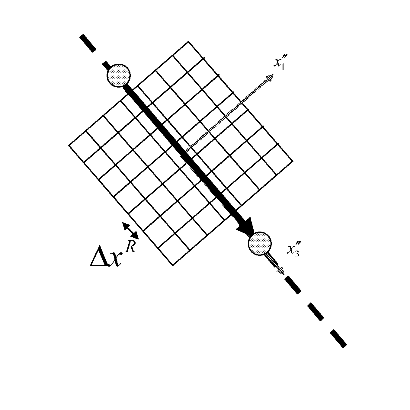
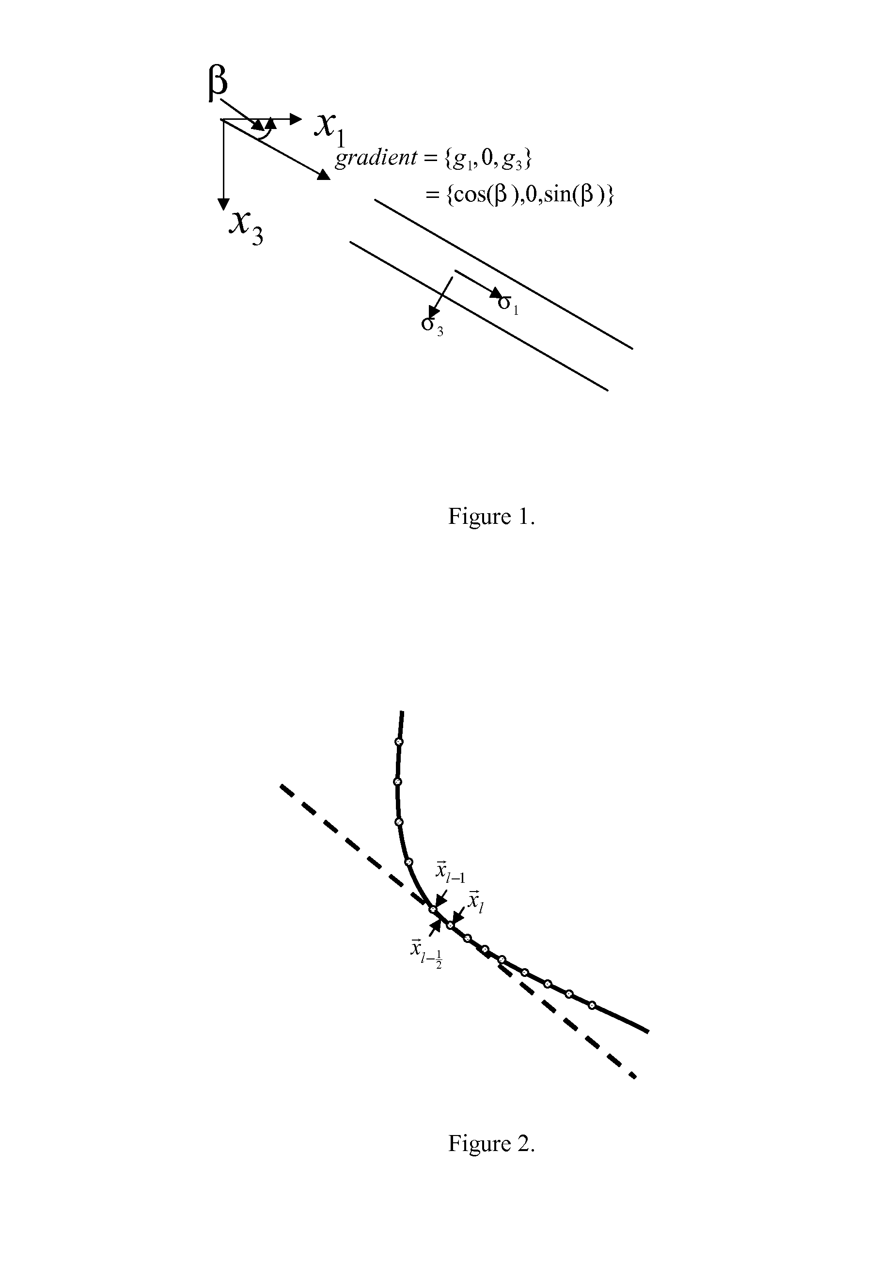
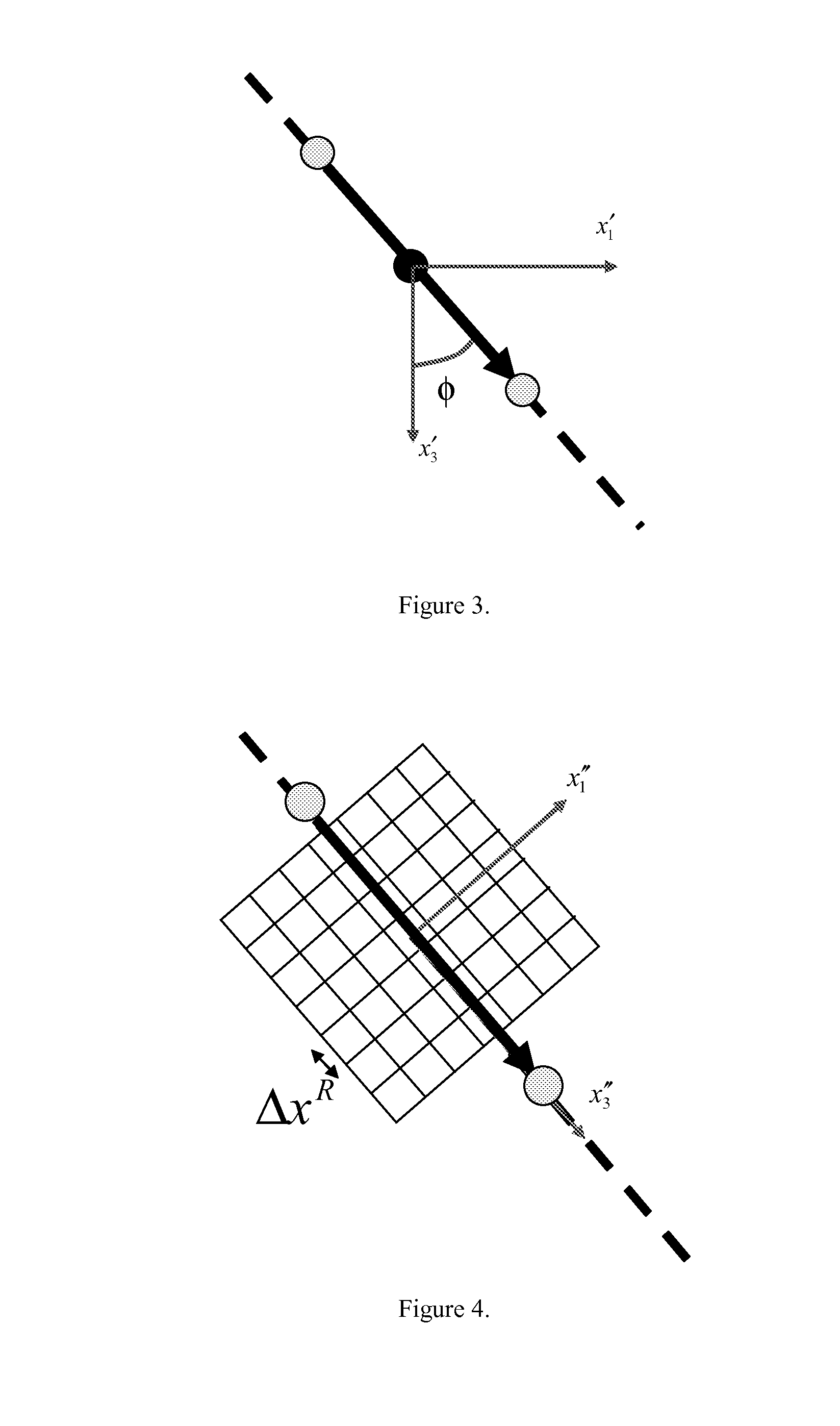
[0024]A medium with anisotropic electrical conductivity is standard described by a matrix. The conductivity matrix in a point {right arrow over (x)}depends on the local medium gradients. For simplicity a 2D medium is considered that is invariant in the x2-direction. Let, for a dipping local layer with biaxial anisotropic conductivity, the three so-called principal axes be denoted by σ1, σ2 and σ3. The principal axes are the conductivities along a rotated local Cartesian reference in this dipping layer (see FIG. 1). Let the medium gradient be given by the vector {g1,0,g3}, where gt=cos(β) and g3=sin(β). Here, β denotes the angle of dipping of the local layer...


PUM


Abstract

There is provided a method of predicting the response of an induction logging tool along an arbitrary trajectory in a three-dimensional earth model, wherein the method comprises a confinement of the electromagnetic field computations to a limited domain of the geology surrounding the induction logging tool. The magnetic field at a receiver coil is considered as a superposition of a primary background constituent and a secondary constituent. A single spherical scatterer approximation is used for the second constituent.

Description

[0001]The invention relates to methods for predicting the response of an induction logging tool along an arbitrary trajectory in a three-dimensional earth model.BACKGROUND OF INVENTION[0002]It is known to produce an induction log which is a log of the conductivity of rock with depth obtained by lowering into a borehole a generating coil that induces eddy currents in the rocks and these are detected by a receiver coil. In the simplest device, an alternating current of medium frequency (100 kHz up to a few MHz) is generated in a source coil, thereby inducing an alternating magnetic field in the formation. This magnetic field creates electric currents in the formation. The electric currents generate their own magnetic fields, which induce again an electric current in the receiver coil. The signal received depends on the electric conductivity of the surrounding earth formation, with contributions from different regions of the formation. An effective computational model is required that ...

Claims


Application Information

Patent Timeline
Patent Type & Authority Applications(United States)
IPC IPC(8): G01V3/28
CPCG01V3/28G01V3/38
Inventor PETERSEN, STEEN AGERLINVAN DEN BERG, PETRUS MARIAFOKKEMA, JACOB TJEERD
Owner DEN NORSKE STATS OLJESELSKAP AS
Why Eureka
Try Eureka