Rotary union for use with a fluid conduit

Inactive Publication Date: 2014-01-30
DANA HEAVY VEHICLE SYSTEMS GROUP LLC
View PDF10 Cites 25 Cited by
  • Summary
  • Abstract
  • Description
  • Claims
  • Application Information

AI Technical Summary

Benefits of technology

[0009]Presently provided by the invention, a rotary union that may be used with a tire inflation system has been developed that permits axial deviation between a rotating component and a n

Problems solved by technology

Such operations add cost to the vehicle the rotary union is incorporated in.
Friction between the resilient seals and the surfaces the seals are engaged with results in excessive drag and heat generation.
Further, a force applied by the reinforcing member is substantially constant regardless of a speed of the rotating component; which may result in the force applied by the reinforcing member to decrease at higher operational spe

Method used


Image

  • Rotary union for use with a fluid conduit
  • Rotary union for use with a fluid conduit
  • Rotary union for use with a fluid conduit

Examples


Example

[0019]It is to be understood that the invention may assume various alternative orientations and step sequences, except where expressly specified to the contrary. It is also to be understood that the specific devices and processes illustrated in the attached drawings, and described in the following specification are simply exemplary embodiments of the inventive concepts defined in the appended claims. Hence, specific dimensions, directions or other physical characteristics relating to the embodiments disclosed are not to be considered as limiting, unless the claims expressly state otherwise.

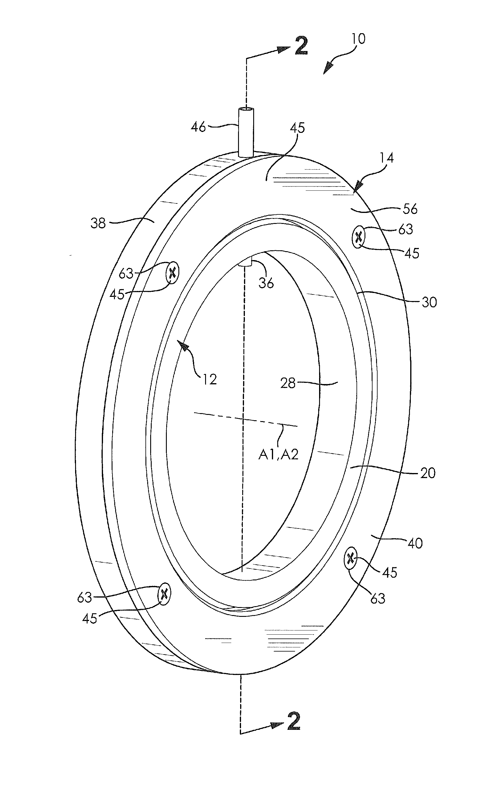
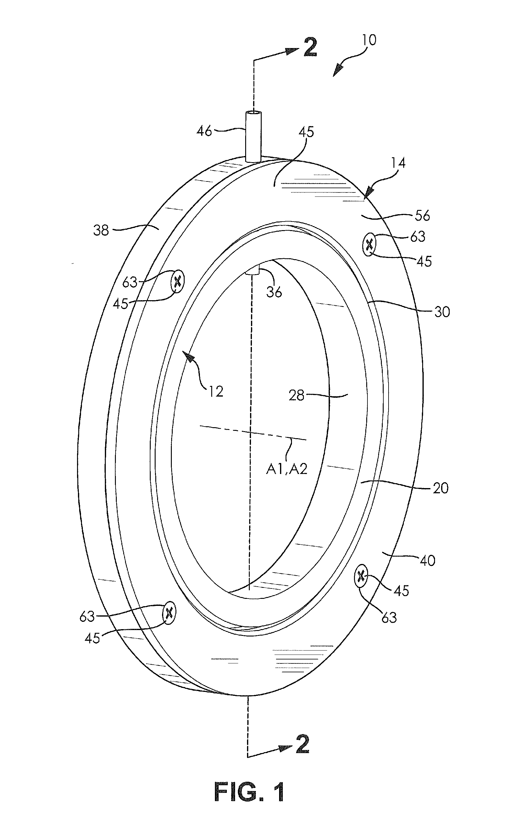
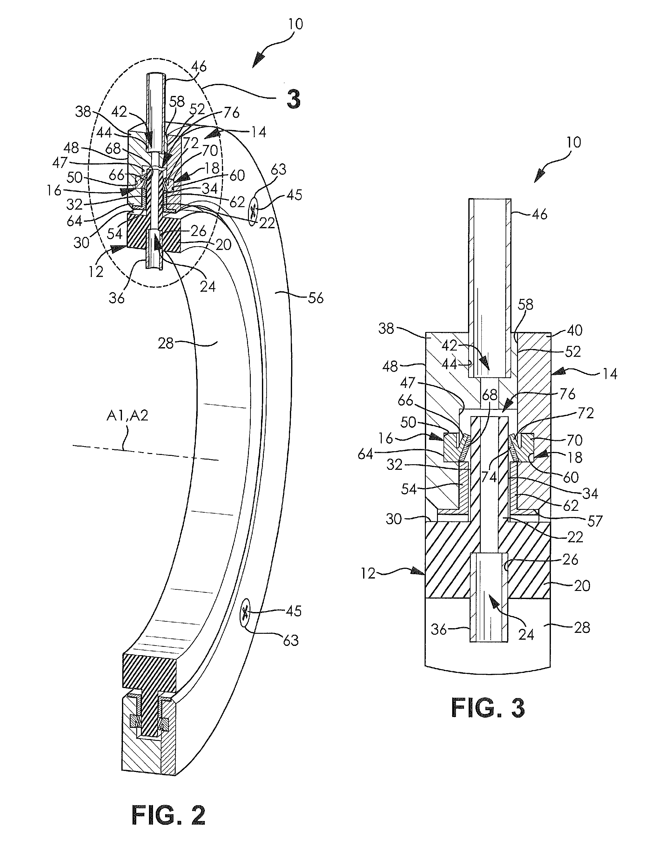
[0020]FIGS. 1-3 illustrate a rotary union 10 according to an embodiment of the invention. The rotary union 10 preferably comprises a first housing portion 12, a second housing portion 14, a first sealing member 16, and a second sealing member 18. As non-limiting examples, the rotary union 10 may form a portion of a tire inflation system (not shown), the rotary union 10 may form a portion of a whee...


PUM


Abstract

A rotary union is provided. The rotary union includes a first housing portion, a second housing portion, and a sealing member. The first housing portion has a first fluid passage formed therein and the second housing portion has a second fluid passage formed therein. The second fluid passage is in fluid communication with the first fluid passage. The sealing member is disposed on one of the first housing portion and the second housing portion and is sealingly engaged with a remaining one of the first housing portion and the second housing portion in a substantially similar direction to an axis of rotation of one of the first housing portion and the second housing portion. The rotary union permits axial deviation between a rotating component and a non-rotating component, reduces friction generated within the rotary union, and permits an increased flow rate of a fluid through the rotary union.

Description


Claims


Application Information

Patent Timeline
Owner DANA HEAVY VEHICLE SYSTEMS GROUP LLC
Why Eureka
Try Eureka