System for detecting a falling electric power conductor and related methods

a technology of electric power conductor and detection system, which is applied in the field of detection system of falling electric power conductor, can solve the problems of igniting fire, flammable materials or vegetation, and electric current electrocution of people or animals in the vicinity of the fallen, and existing electrical protective systems and methods often fail to detect that a live conductor has contacted the ground

Active Publication Date: 2014-01-30
SAN DIEGO GAS & ELECTRIC COMPANY
View PDF2 Cites 36 Cited by
  • Summary
  • Abstract
  • Description
  • Claims
  • Application Information

AI Technical Summary

Benefits of technology

[0005]A contribution to the art would include measuring devices that can detect a falling conductor situation at the moment it first occurs or shortly thereafter and trips a substation circuit breaker or circuit interrupting device and de-energize the hazardous circuit before the conductor falls to the ground resulting in a ground fault.

Problems solved by technology

An overhead high-voltage electric power distribution conductor may, for a variety of reasons (e.g., pole knocked over, tree fall, pole mounted conductor clamp failure, etc.), become detached or damaged and may fall to the ground while it remains energized, resulting in a ground fault.
The arcing can ignite flammable materials or vegetation and start a fire, and the flow of electric current may electrocute a person or animal in the vicinity of the fallen conductor.
Existing electrical protective systems and methods frequently fail to detect that a live conductor has contacted the ground.
In favorable situations (e.g., high earth conductivity) where existing methods do detect the disconnected conductor on the ground, they do so only after the conductor has begun arcing on the ground, posing a high risk that a fire has already been ignited or persons nearby have been electrocuted.
Fallen-conductor ground faults, even when visibly dramatic at the site of ground contact, may not produce sufficiently distinguishable and detectable electrical measurement changes at the substation.
Furthermore, even when the fault produces currents or signatures that can be detected, the detection and de-energization process may take relatively too long, in the order of 200 ms to several seconds or even minutes (several seconds to minutes is more typical).

Method used


Image

  • System for detecting a falling electric power conductor and related methods
  • System for detecting a falling electric power conductor and related methods
  • System for detecting a falling electric power conductor and related methods

Examples


Embodiment Construction

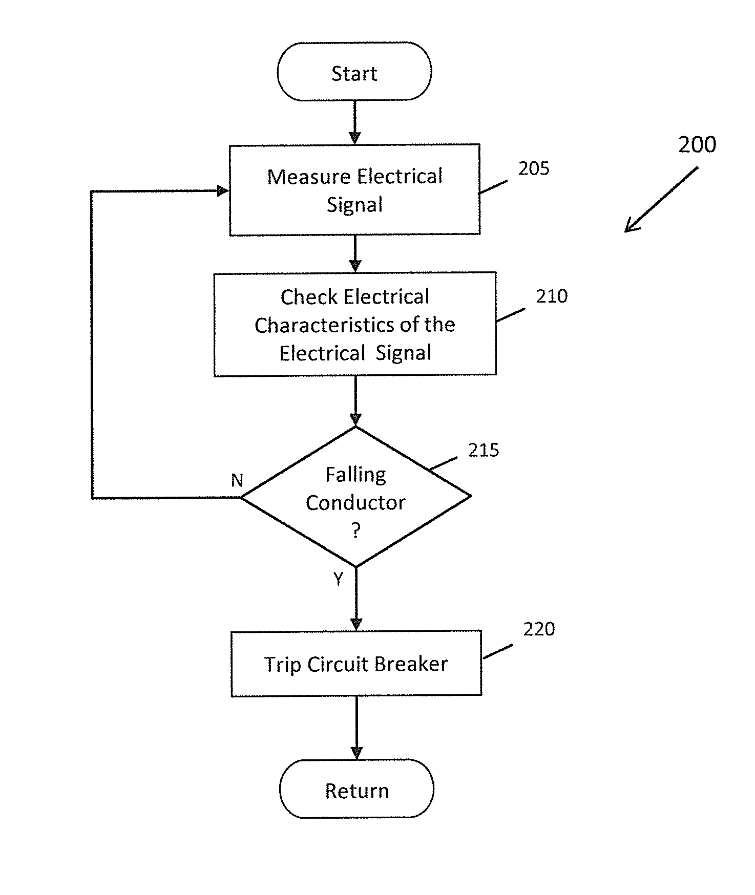
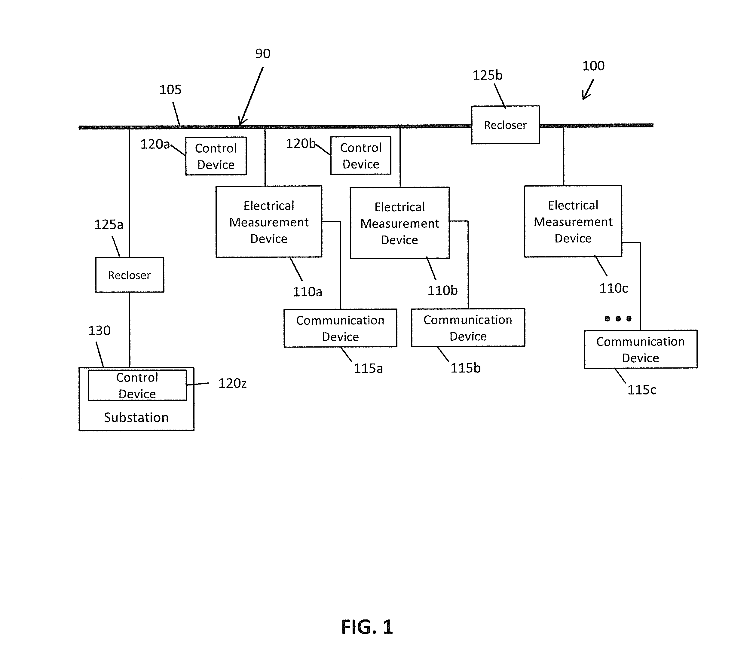
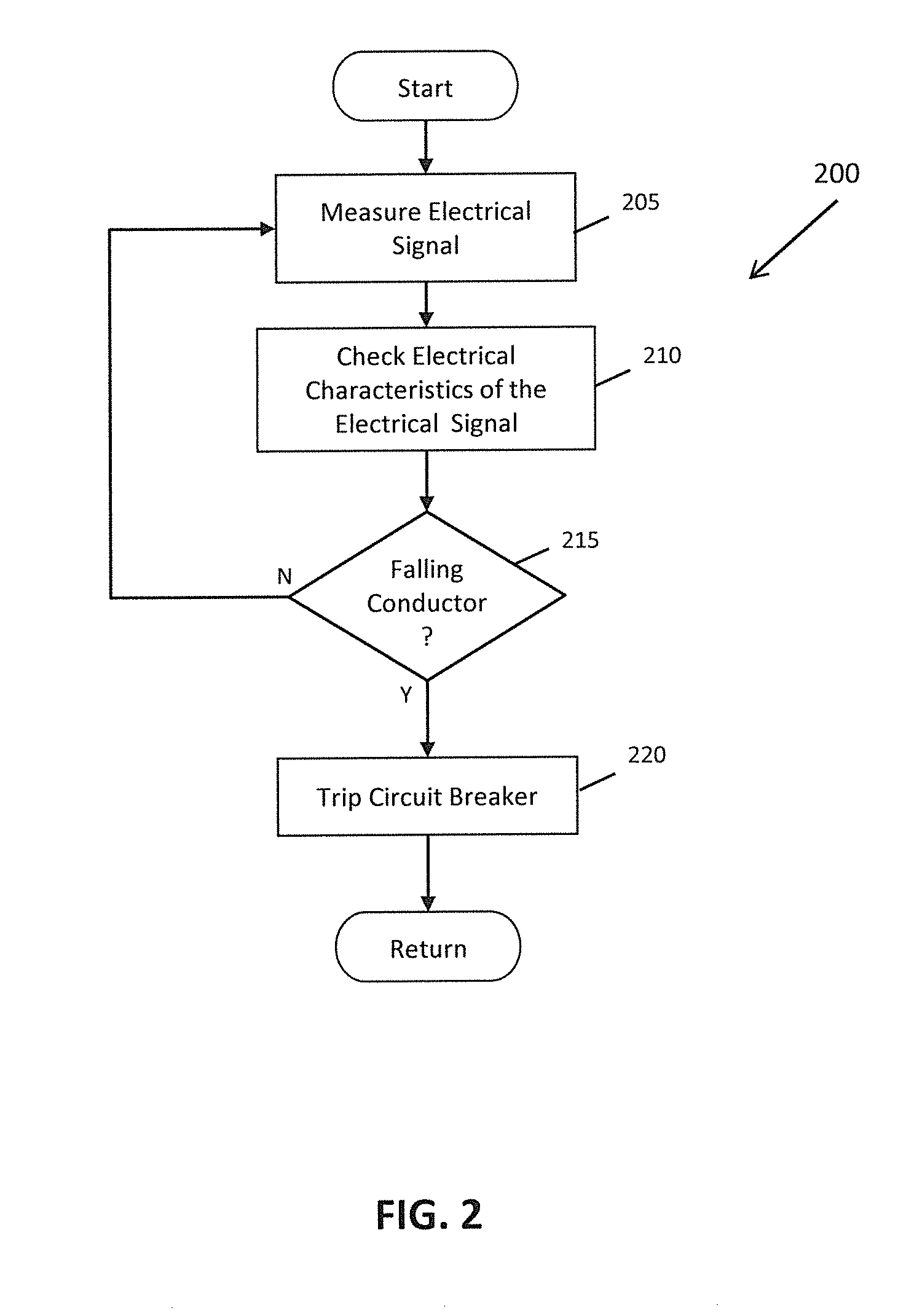
[0022]The detailed description set forth below in connection with the appended drawings is intended as a description of the presently preferred embodiments of signature detection and deenergization systems and methods provided in accordance with aspects of the present disclosure, which are usable on either electrical distribution system, electrical transmission system, or both, and is not intended to represent the only forms in which the present device, system, and method may be constructed or utilized. The description sets forth the features and the steps for constructing and using the embodiments of the present device, system, and method in connection with the illustrated embodiments. It is to be understood, however, that the same or equivalent functions and structures may be accomplished by different embodiments that are also intended to be encompassed within the spirit and scope of the present disclosure. As denoted elsewhere herein, like element numbers are intended to indicate...


PUM


Abstract

Methods and systems for detecting a falling power line in a power transmission or distribution system are described. Electrical measurements at various points in the power distribution system are used to detect changes in a power line indicating that the conductor has broken or become disconnected. Upon detection, control mechanisms are used to deenergize the conductor while the conductor is falling and/or before it contacts the ground.

Description

FIELD OF ART[0001]Aspects of the present disclosure relate to fault anticipation or detection in or as part of a power grid, and more particularly to methods and systems for using measurements to detect changes in a power line indicating that the power transmission or distribution conductor has broken or become disconnected. Further aspects of the present device, system, and method include control mechanisms to deenergize the conductor while the conductor is falling and / or before it contacts the ground or other objects. Still further aspects of the present device, system, and method include control mechanisms for detecting a disconnected conductor and de-energizing the disconnected conductor.BACKGROUND[0002]An overhead high-voltage electric power distribution conductor may, for a variety of reasons (e.g., pole knocked over, tree fall, pole mounted conductor clamp failure, etc.), become detached or damaged and may fall to the ground while it remains energized, resulting in a ground f...

Claims


Application Information

Patent Timeline
Patent Type & Authority Applications(United States)
IPC IPC(8): H02H3/02
CPCH02H3/02H02H3/04H02H3/26H02H3/265H02H3/32H02H3/325H02H3/353H02H3/38H02H3/422H02H3/44H02H3/46H02H3/48H02H7/261H02H7/28Y02E40/70Y02E60/00Y04S10/00Y04S10/22H02H7/263
Inventor O'BRIEN, WILLIAMUDREN, ERIC A.
Owner SAN DIEGO GAS & ELECTRIC COMPANY
Why Eureka
Try Eureka