Moving Magnet Actuator with Counter-Cogging End-Ring and Asymmetrical Armature Stroke

a magnet actuator and end-ring technology, applied in the field of actuators, can solve the problems of affecting the effect of a lower pull force acting on the armature when, the armature will not reach its full translation position, and the subtraction effect is particularly undesirable, so as to achieve the effect of less susceptible to cogging forces and/or lower pull forces

Inactive Publication Date: 2014-01-30
WOODWARD GOVERNOR CO
View PDF9 Cites 17 Cited by
  • Summary
  • Abstract
  • Description
  • Claims
  • Application Information

AI Technical Summary

Problems solved by technology

This subtractive effect is particularly undesirable.
If the spring bias is not overcome, the armature will not reach its fully translated position.
Another drawback of conventional MMA design is the impact a lower pull force has acting on the armature when it is displaced from the center of the magnetically conductive conduit.
This is particularly problematic for MMAs not intended to operate bi-directionally.

Method used


Image

  • Moving Magnet Actuator with Counter-Cogging End-Ring and Asymmetrical Armature Stroke
  • Moving Magnet Actuator with Counter-Cogging End-Ring and Asymmetrical Armature Stroke
  • Moving Magnet Actuator with Counter-Cogging End-Ring and Asymmetrical Armature Stroke

Examples


Embodiment Construction

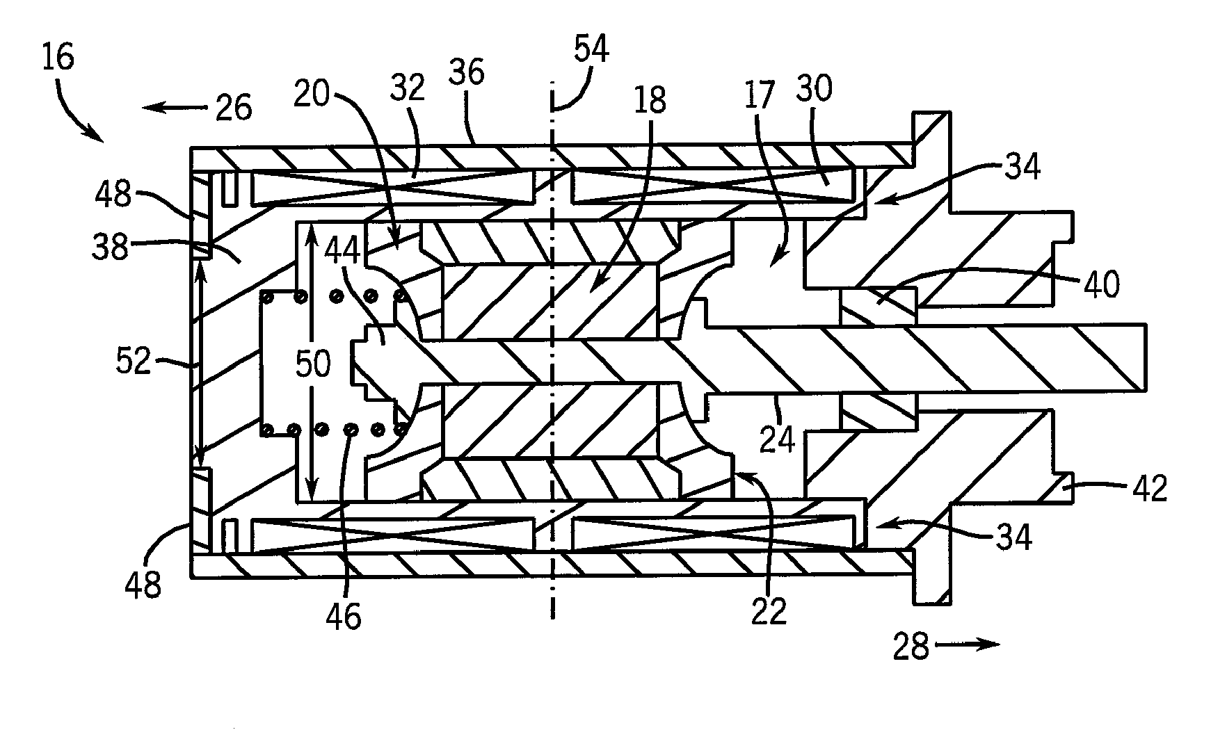
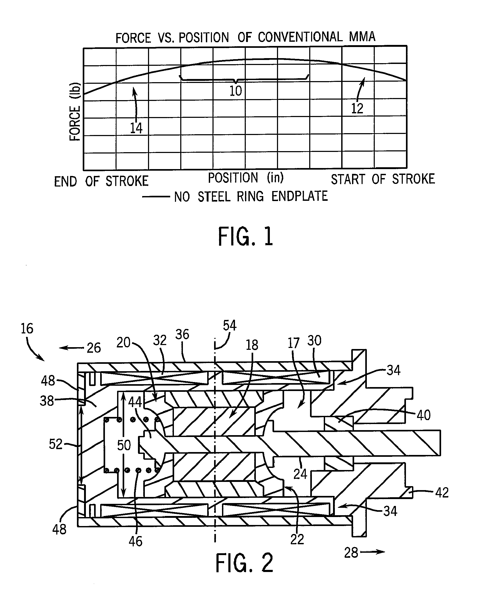
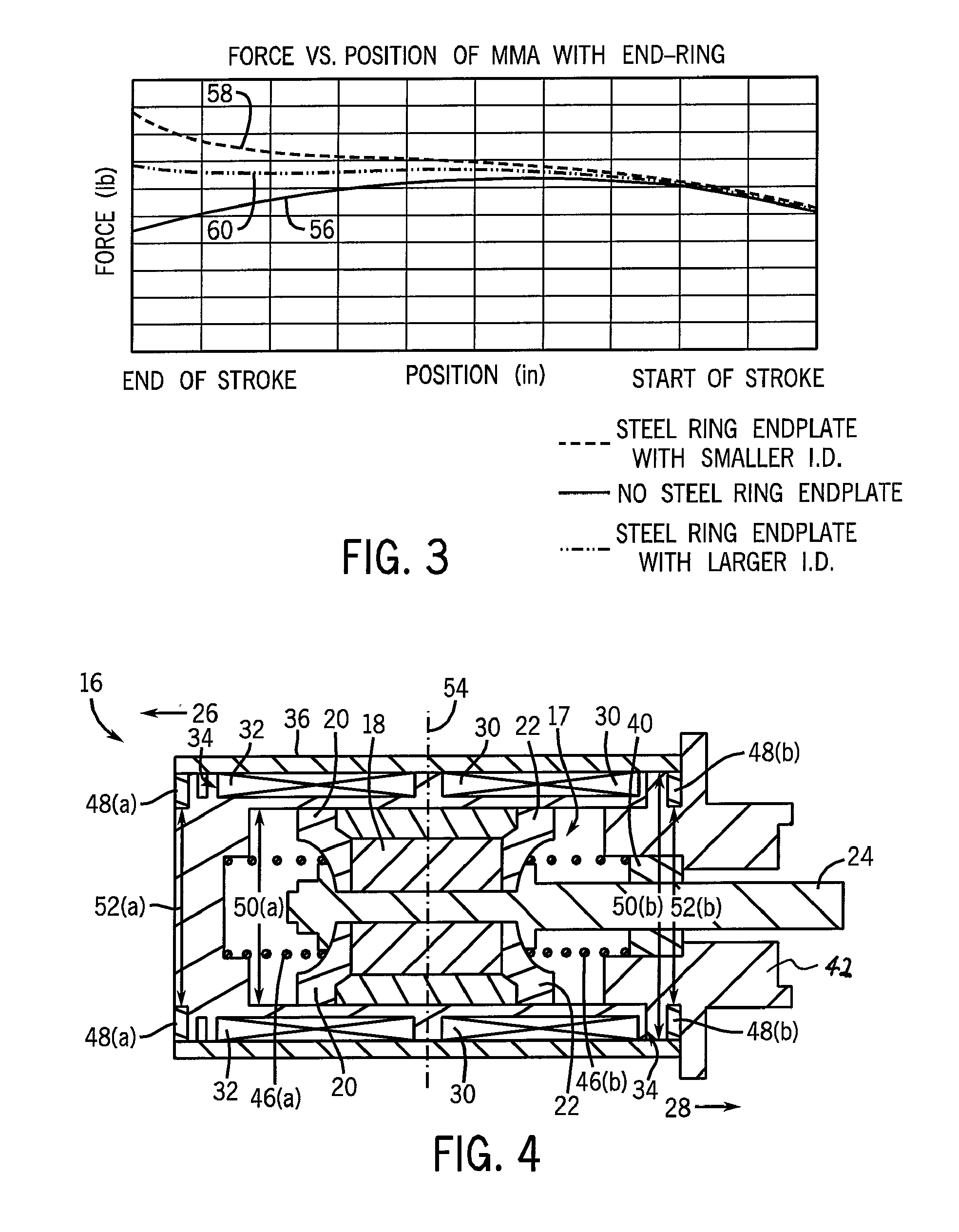
[0027]An exemplary MMA according to one embodiment of the invention is shown in cross-section in FIG. 2. As will be explained in greater detail below, the MMA is constructed to exert a counter or anti-cogging force. The MMA 16 is similar to conventional MMA design in that an armature 17 is designed to have a permanent magnetic ring 18 sandwiched between two magnetically conductive pole end pieces 20, 22 that are affixed to a shaft 24 fabricated of non-conductive material. The ring magnet is preferably a sintered, anisotropic, axially-oriented permanent magnet. Shaft 24 travels in both the positive and negative directions 26, 28, respectively, by an electromotive force produced by two in-series, oppositely wound, coils (windings) 30, 32. The coils 30, 32 are located in the radial air gap 34 between the outer diameter of the magnetically conductive pole pieces 20, 22 and the inner diameter of the magnetically conductive conduit 36. The coils 30, 32 are supported by bobbin 38. Similar ...


PUM

PropertyMeasurementUnit
inner diameteraaaaaaaaaa
spring forceaaaaaaaaaa
magnetic fieldaaaaaaaaaa

Abstract

A moving magnet actuator (MMA) includes a magnetically conductive end-ring that is spaced from a magnet pole piece. The end-ring is constructed and spaced to provide a desired counter or anti-cogging force when the MMA is in a powered state. The MMA is also constructed such that a central portion of its armature stroke is axially displaced from a radial centerline of the magnetically conductive conduit enclosing the MMA components.

Description

CROSS REFERENCE TO RELATED APPLICATION[0001]The present application is a continuation of and claims priority of U.S. Provisional Patent Application Ser. No. 60 / 743,463 filed Mar. 13, 2006, the disclosure of which is incorporated herein by reference.BACKGROUND OF THE INVENTION[0002]The present invention relates generally to actuators and, more particularly, to a moving magnet actuator (MMA) having an end-ring that provides a counter or anti-cogging force and an asymmetrical armature stroke.[0003]Moving magnet actuators generally comprise an armature containing a sintered, anisotropic, axially-oriented, permanent ring magnet sandwiched between two magnetically conductive pole end pieces that are affixed to a non-conductive shaft. When an electromotive force is imparted on the permanent magnet such as by two in-series, oppositely wound, coils located in a radial air gap between the outer diameter of the magnetically conductive pole pieces and the inner diameter of a magnetically conduc...

Claims


Application Information

Patent Timeline
Patent Type & Authority Applications(United States)
IPC IPC(8): H01F7/16
CPCH01F7/1615H02K33/16
Inventor SCANLON, MATTHEW J.
Owner WOODWARD GOVERNOR CO
Why Eureka
Try Eureka