Wide-angle optical lens assembly

a technology of optical lenses and components, applied in the field of wide-angle optical lens assemblies, can solve the problems of insufficient field of view to capture wide-angle images, inability to efficiently correct aberration due to wide-angle, and no longer meet the requirements of high-quality photographs

Active Publication Date: 2014-01-30
LARGAN PRECISION
View PDF1 Cites 47 Cited by
  • Summary
  • Abstract
  • Description
  • Claims
  • Application Information

AI Technical Summary

Benefits of technology

[0033]The second lens element with refractive power has a concave object-side surface and a convex image-side surface for balancing the aberration caused by the first lens element operated in a large field of view condition and solving problems such as the insufficient brightness of surrounded images. Furthermore, the second lens element can have at least one inflection point on at least one of the surfaces thereof, so that the incident angle of the off-axis field on an image sensor can be effectively minimized, and the aberration of the off-axis field can be corrected as well.

Problems solved by technology

The conventional four-element lens structure, therefore, no longer satisfies the requirements of high quality photograph.
Although the optical systems with five-element lens structure, such as optical systems with five-element lens structure disclosed in U.S. Pat. No. 8,000,030 and U.S. Pat. No. 8,000,031, have been developed recently, the field of view is too insufficient to capture wide-angle images.
In addition, as the wide-angle optical systems with five-element lens structure disclosed in US Application No. 2012 / 0069140, the aberration due to wide-angle is unable to be corrected efficiently by designing the five-element lens.
On the other hand, since the insufficient brightness of the surrounded image problem also exists in the five-element lens design, the image quality is unable to be raised efficiently.

Method used


Image

  • Wide-angle optical lens assembly
  • Wide-angle optical lens assembly
  • Wide-angle optical lens assembly

Examples


first embodiment

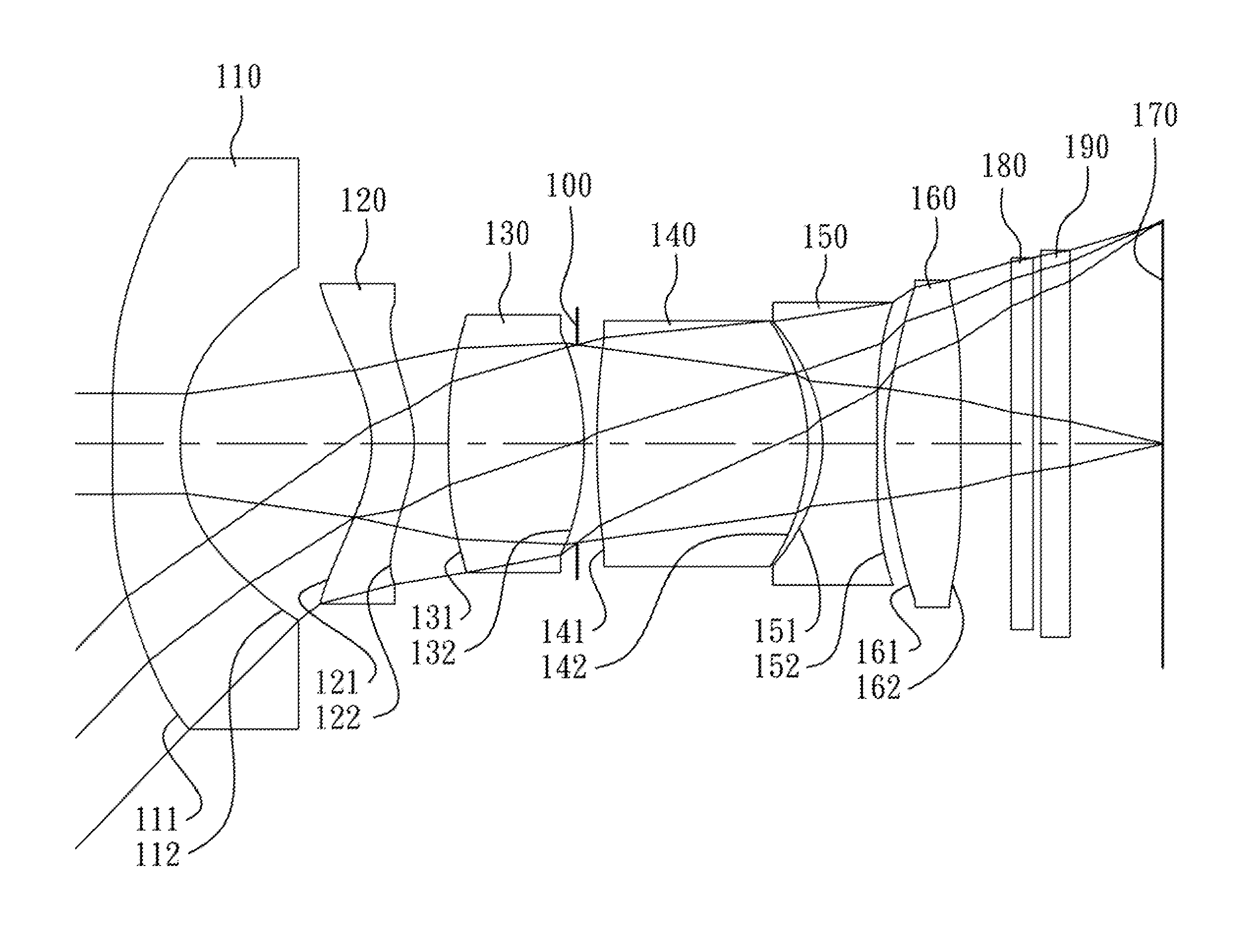
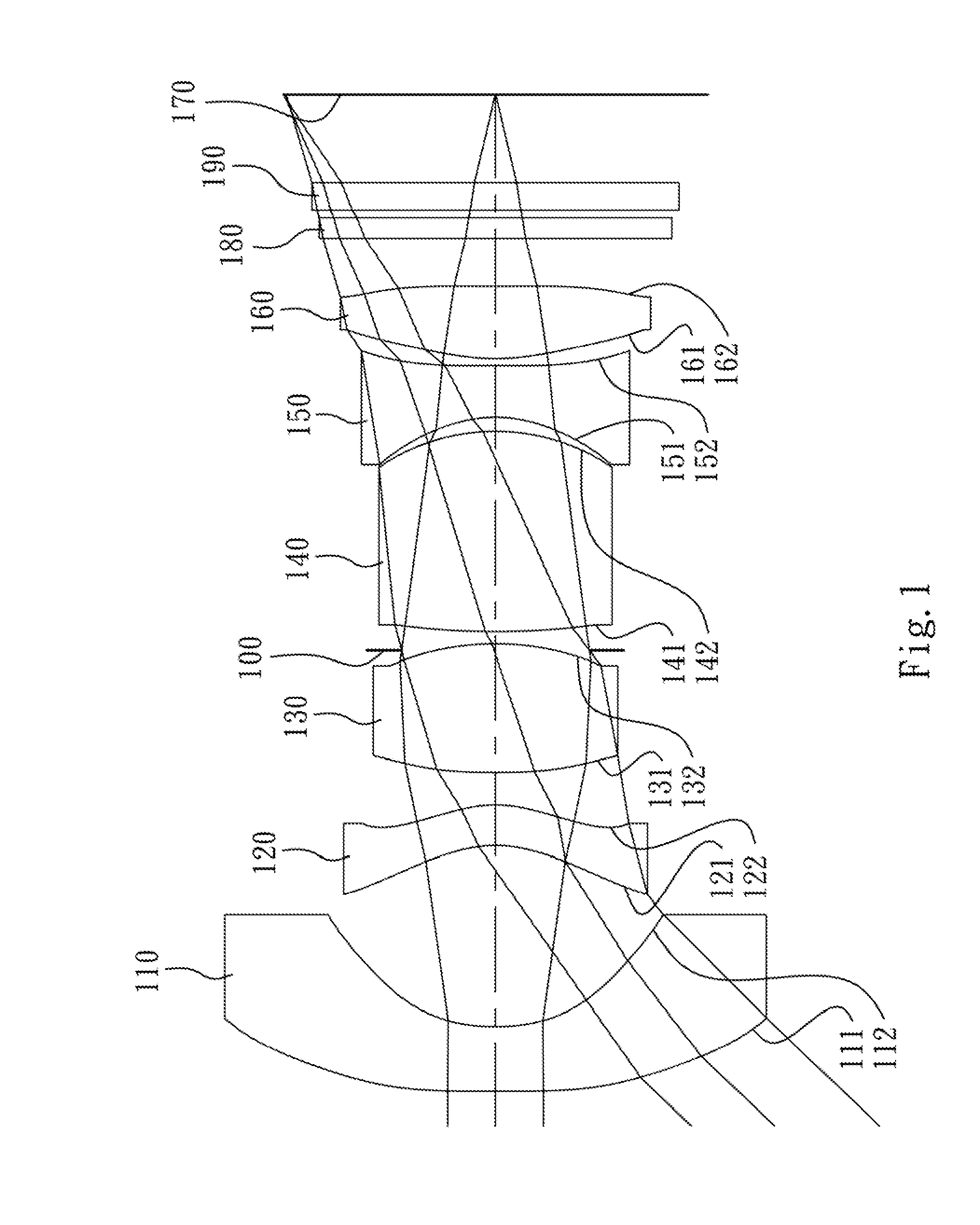
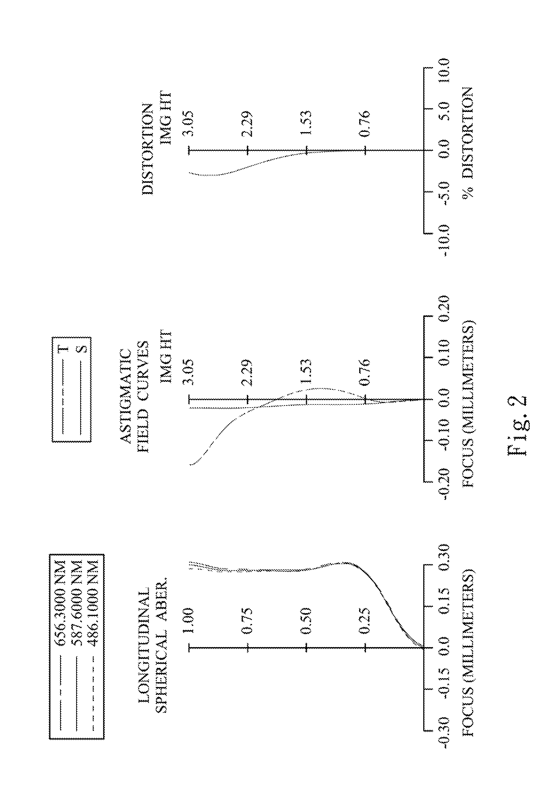
[0074]FIG. 1 is a schematic diagram of a wide-angle optical lens assembly according to the 1st embodiment of the present disclosure. FIG. 2 shows spherical aberration curves, astigmatic field curves and a distortion curve of the wide-angle optical lens assembly according to the 1st embodiment. In FIG. 1, the wide-angle optical lens assembly includes, in order from an object side to an image side, a first lens element 110, a second lens element 120, a third lens element 130, an aperture stop 100, a fourth lens element 140, a fifth lens element 150, a sixth lens element 160, an IR-cut filter 180, a cover glass 190, and an image plane 170. The first lens element 110, the second lens element 120, and the third lens element 130 are belonged to a front lens group, and the fourth lens element 140, the fifth lens element 150, and the sixth lens element 160 are belonged to a rear lens group.

[0075]The first lens element 110 with negative refractive power has a concave object-side surface 111 ...

2nd embodiment

[0104]FIG. 3 is a schematic diagram of a wide-angle optical lens assembly according to the 2nd embodiment of the present disclosure. FIG. 4 shows spherical aberration curves, astigmatic field curves and a distortion curve of the wide-angle optical lens assembly according to the 2nd embodiment. In FIG. 3, the wide-angle optical lens assembly includes, in order from an object side to an image side, a first lens element 210, a second lens element 220, a third lens element 230, an aperture stop 200, a fourth lens element 240, a fifth lens element 250, a sixth lens element 260, an IR-cut filter 280, a cover glass 290, and an image plane 270. The first lens element 210, the second lens element 220, and the third lens element 230 are belonged to a front lens group, and the fourth lens element 240, the fifth lens element 250, and the sixth lens element 260 are belonged to a rear lens group.

[0105]The first lens element 210 with negative refractive power has a convex object-side surface 211 a...

3rd embodiment

[0114]FIG. 5 is a schematic diagram of a wide-angle optical lens assembly according to the 3rd embodiment of the present disclosure. FIG. 6 shows spherical aberration curves, astigmatic field curves and a distortion curve of the wide-angle optical lens assembly according to the 3rd embodiment. In FIG. 5, the wide-angle optical lens assembly includes, in order from an object side to an image side, a first lens element 310, a second lens element 320, a stop 301, a third lens element 330, an aperture stop 300, a fourth lens element 340, a fifth lens element 350, a sixth lens element 360, an IR-cut filter 380, a cover glass 390, and an image plane 370. The first lens element 310, the second lens element 320, and the third lens element 330 are belonged to a front lens group, and the fourth lens element 340, the fifth lens element 350, and the sixth lens element 360 are belonged to a rear lens group.

[0115]The first lens element 310 with negative refractive power has a concave object-side ...


PUM

PropertyMeasurementUnit
angleaaaaaaaaaa
refractive poweraaaaaaaaaa
focal lengthaaaaaaaaaa

Abstract

A wide-angle optical lens assembly includes, in order from an object side to an image side, a first lens element, a second lens element, a third lens element, a fourth lens element, a fifth lens element, and a sixth lens element. The first lens element with negative refractive power has a concave image-side surface. The second lens element with refractive power has a concave object-side surface and a convex image-side surface. The third lens element has positive refractive power. The fourth lens element has positive refractive power. The fifth lens element with refractive power has an object-side surface and an image-side surface which both are aspheric. The sixth lens element with refractive power has a convex object-side surface, wherein the object-side surface and an image-side surface thereof are both aspheric. At least one of the second lens element and the fifth lens element has at least one inflection point.

Description

RELATED APPLICATIONS[0001]This application claims priority to Taiwan Application Serial Number 10126647, filed Jul. 24, 2012, which is herein incorporated by reference.BACKGROUND[0002]1. Technical Field[0003]The present disclosure relates to a wide-angle optical lens assembly. More particularly, the present disclosure relates to a compact wide-angle optical lens assembly applicable to electronic products.[0004]2. Description of Related Art[0005]In recent years, as the popularity of mobile electronic products with camera functionalities developed, the requirement for miniaturizing an image lens system is increasing. The sensor of a conventional photographing camera is typically a CCD (Charge Coupled Device) image sensor or a CMOS (Complementary Metal-Oxide Semiconductor) sensor. Since the semiconductor manufacturing technologies are advancing, the pixel size of sensors is reducing, and compact image lens system has gradually evolved toward the field of higher megapixels. Therefore, r...

Claims


Application Information

Patent Timeline
Patent Type & Authority Applications(United States)
IPC IPC(8): G02B13/18
CPCG02B13/06G02B13/0045G02B1/04
Inventor LIAO, LIN-YAOHUANG, HSIN-HSUAN
Owner LARGAN PRECISION
Why Eureka
Try Eureka