
Image Pick-Up Lens System and Module and Terminal Therefor

a technology of image pickup and lens system, which is applied in the field of lens imaging optical system, can solve the problems of not being able to further shorten the system length, and achieve the effects of reducing the aberration influence of the lens system, shortening the lens system length, and miniaturizing the lens

Active Publication Date: 2017-04-06
ZHEJIANG SUNNY OPTICAL CO LTD
View PDF1 Cites 12 Cited by
  • Summary
  • Abstract
  • Description
  • Claims
  • Application Information

AI Technical Summary

Benefits of technology

The present invention provides an image pick-up lens system and an imaging module that can be used to capture high-resolution and high-quality photographic images. The system has a positive, negative, and negative lens combination that reduces the length and size of the lens system, while effectively correcting off-axis aberration and improving image quality. The image-side surface of the fifth lens is a convex surface, and the focal power allocation is effective in balancing the system, reducing off-axis aberration, and improving image quality. The lenses are made of plastic, with at least one lens surface being an aspherical surface to improve aberration correction and imaging quality. The imaging module can be used in portable terminals to capture high-resolution and high-quality photographic images.

Problems solved by technology

However, with the known five-lens structure, it is not possible to further shorten the system length and meet the requirement for image quality in a large aperture diameter configuration.

Method used


Image

  • Image Pick-Up Lens System and Module and Terminal Therefor
  • Image Pick-Up Lens System and Module and Terminal Therefor
  • Image Pick-Up Lens System and Module and Terminal Therefor

Examples


embodiment 1

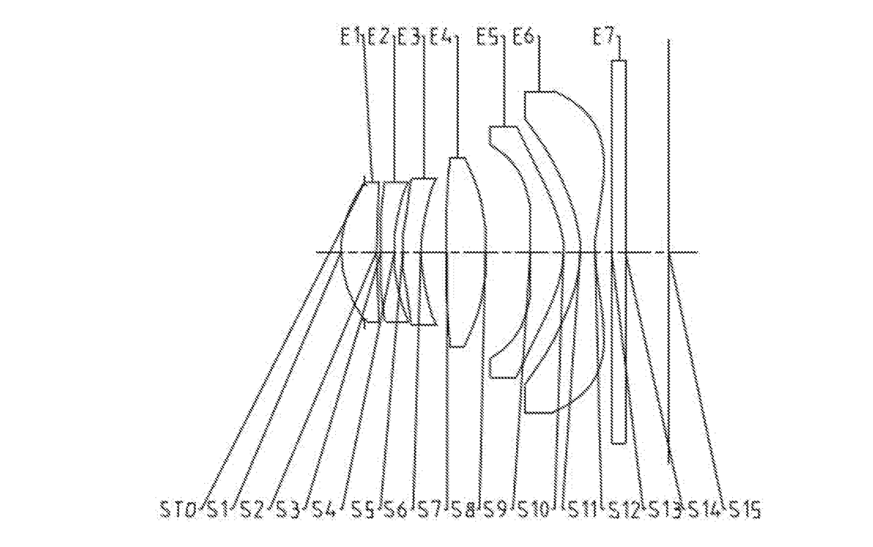
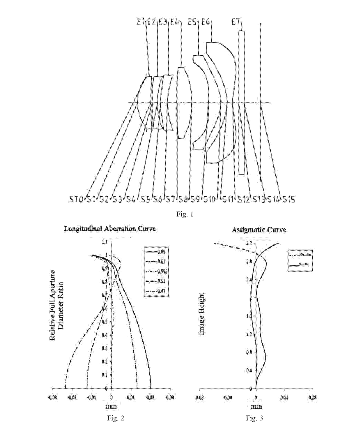
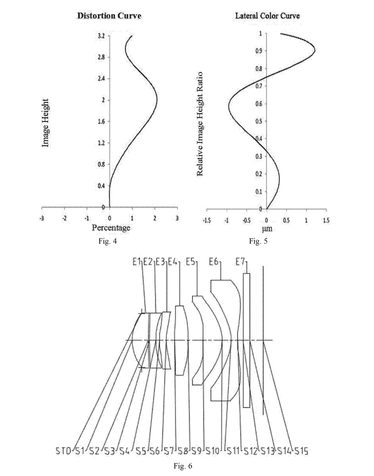
[0060]As shown in FIG. 1, the image pick-up lens system provided in Embodiment 1 of the present invention comprises the following components arranged sequentially from the object side to the image side: a diaphragm, a first lens E1, a second lens E2, a third lens E3, a fourth lens E4, a fifth lens E5, a sixth lens E6, a filter lens E7, and an imaging plane. The first lens E1 has positive focal power, with a convex object-side surface; the second lens E2 has negative focal power, with a convex object-side surface; the third lens E3 has negative focal power, with a concave image-side surface; the image-side surface of the fourth lens E4 is a convex surface; the fifth lens E5 has positive focal power, with a convex image-side surface, and the positive focal power near the optical axis turns to be negative focal power towards the circumference; the sixth lens E6 has positive focal power at the circumference, with a concave image-side surface near the optical axis. In the image pick-up l...

embodiment 2

[0065]As shown in FIG. 6, the image pick-up lens system provided in Embodiment 2 of the present invention comprises the following components arranged sequentially from the object side to the image side: a diaphragm, a first lens E1, a second lens E2, a third lens E3, a fourth lens E4, a fifth lens E5, a sixth lens E6, a filter lens E7, and an imaging plane. The first lens E1 has positive focal power, with a convex object-side surface; the second lens E2 has negative focal power, with a convex object-side surface; the third lens E3 has negative focal power, with a concave image-side surface; the image-side surface of the fourth lens E4 is a convex surface; the fifth lens E5 has positive focal power, with a convex image-side surface, and the positive focal power near the optical axis turns to be negative focal power towards the circumference; the sixth lens E6 has positive focal power at the circumference, with a concave image-side surface near the optical axis. In the image pick-up l...

embodiment 3

[0070]As shown in FIG. 11, the image pick-up lens system provided in Embodiment 3 of the present invention comprises the following components arranged sequentially from the object side to the image side: a diaphragm, a first lens E1, a second lens E2, a third lens E3, a fourth lens E4, a fifth lens E5, a sixth lens E6, a filter lens E7, and an imaging plane. The first lens E1 has positive focal power, with a convex object-side surface; the second lens E2 has negative focal power, with a convex object-side surface; the third lens E3 has negative focal power, with a concave image-side surface; the image-side surface of the fourth lens E4 is a convex surface; the fifth lens E5 has positive focal power, with a convex image-side surface, and the positive focal power near the optical axis turns to be negative focal power towards the circumference; the sixth lens E6 has positive focal power at the circumference, with a concave image-side surface near the optical axis. In the image pick-up ...


PUM

PropertyMeasurementUnit
focal poweraaaaaaaaaa
focal lengthaaaaaaaaaa
total lengthaaaaaaaaaa

Abstract

The present invention provides an image pick-up lens system, an imaging module having the image pick-up lens system, and a terminal having the imaging module. The image pick-up lens system comprises the following lenses arranged sequentially from an object side to an image side: a first lens with positive focal power; a second lens with negative focal power, having a convex object-side surface; a third lens with negative focal power; a fourth lens with focal power; a fifth lens with positive focal power, having a convex image-side surface; and a sixth lens with focal power, having a concave image-side surface near an optical axis, wherein, the lenses meet the following relational expression: 5.5<f1.2.3 / Dr1r6<10, where, f1.2.3 is a combined focal length of the first lens, second lens, and third lens; Dr1r6 is a spacing from an object-side surface of the first lens to an image-side surface of the third lens on the optical axis. The lens system provided in the present invention employs six plastic aspherical lenses; by menas of a proper focal power allocation and in a large aperture diameter configuration, the length of the lens system is effectively shortened, the aberration influence is reduced, and the imaging quality of the lens system is improved.

Description

TECHNICAL FIELD[0001]The present invention relates to a lens imaging optical system, in particular to an image pick-up lens system composed of six sets of lenses.BACKGROUND OF THE INVENTION[0002]In recent years, with the development of chip technologies, such as those for CCD or CMOS, the pixel sizes of chips become smaller and smaller, and the requirement for the imaging quality of the associated optical system becomes higher and higher. As a result, the image pick-up lens system has been developed gradually towards a trend of higher pixel resolution and miniaturization. To adapt to that trend, it is further necessary for the optical lenses mounted on electronic products, such as cell phones or digital cameras, to have a high resolution and other properties.[0003]At present, ordinary high-pixel thin lens systems often employ a five-lens structure. For example, the lens system disclosed in the U.S. Pat. No. U.S. 8,411,376B2 comprises the following lenses arranged sequentially from t...

Claims


Application Information

Patent Timeline
Patent Type & Authority Applications(United States)
IPC IPC(8): G02B13/00G02B9/62G02B1/04
CPCG02B13/0045G02B9/62G02B1/041
Inventor DAI, FUJIANHUANG, LIN
Owner ZHEJIANG SUNNY OPTICAL CO LTD
Learn More