Trans-Aortic Surgical Syringe-Type Device for Deployment of a Prosthetic Valve

a prosthetic valve and transaortic surgery technology, applied in the field of prosthetic valve introducer systems, can solve the problems of prolonged patient hospitalization, extensive and often painful recovery, etc., and achieve the effect of accurate deployment, quick, single-shot and accurate implantation of the prosthetic valv

Inactive Publication Date: 2014-01-30
MEDTRONIC VSACULAR GALWAY
View PDF37 Cites 13 Cited by
  • Summary
  • Abstract
  • Description
  • Claims
  • Application Information

AI Technical Summary

Benefits of technology

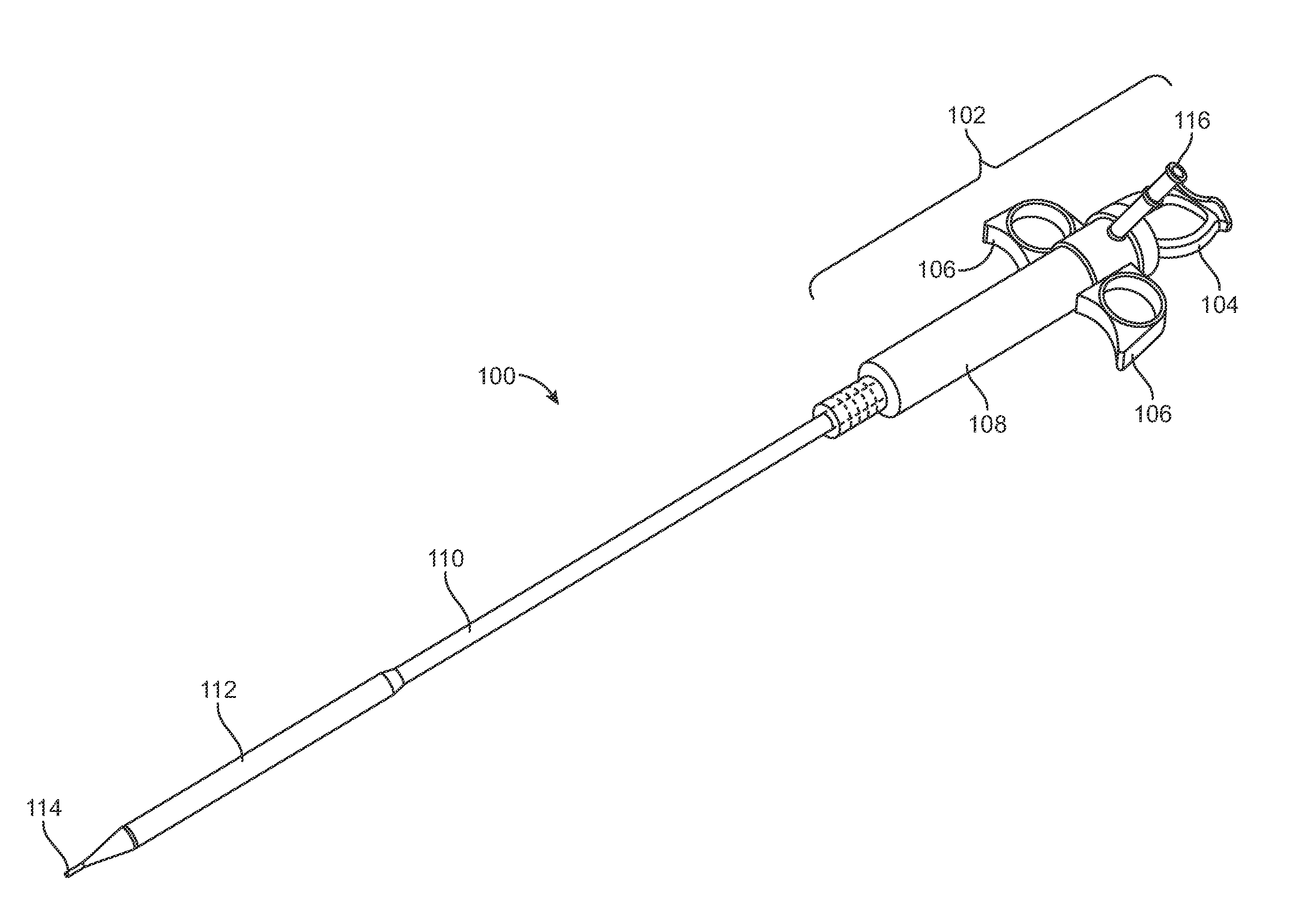
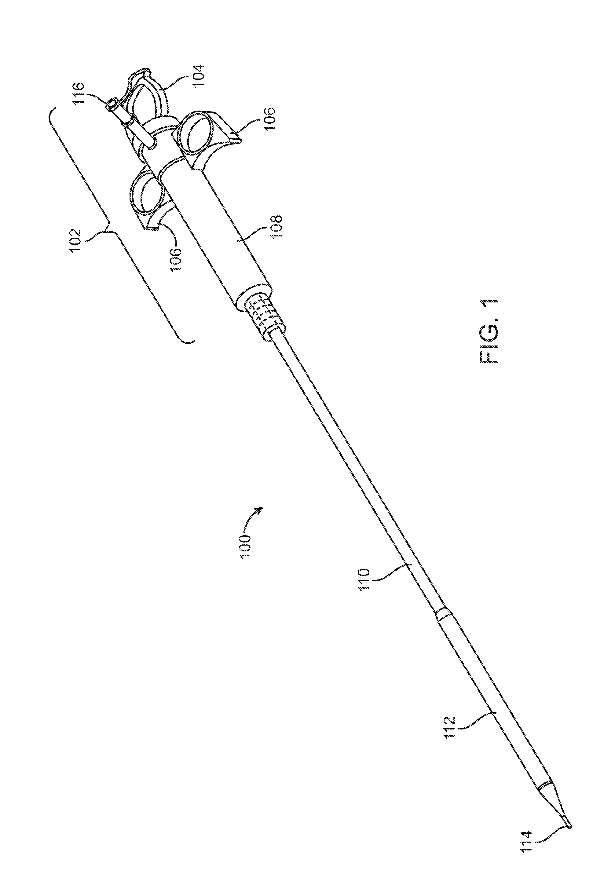
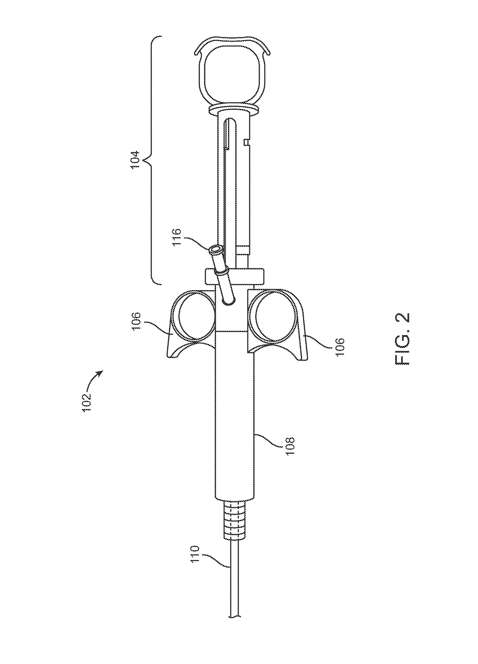
[0009]The present disclosure describes valve introducer systems for implanting a heart valve prosthesis through a trans-aortic pathway. By directly accessing the aorta, it is possible to accurately implant a prosthetic valve without the need for cardiopulmonary bypass, although the disclosed valve introducer systems can also be used with cardiopulmonary bypass. Furthermore, the valve introducer systems disclosed herein allow for one-handed deployment of the prosthetic valve, providing a quick, single-shot and accurate deployment.

Problems solved by technology

This procedure generally requires prolonged patient hospitalization, as well as extensive and often painful recovery.
However, in certain instances it may still be necessary to use the classic sternotomy technique.

Method used


Image

  • Trans-Aortic Surgical Syringe-Type Device for Deployment of a Prosthetic Valve
  • Trans-Aortic Surgical Syringe-Type Device for Deployment of a Prosthetic Valve
  • Trans-Aortic Surgical Syringe-Type Device for Deployment of a Prosthetic Valve

Examples


Embodiment Construction

[0018]While the disclosure refers to illustrative embodiments for particular applications, it should be understood that the disclosure is not limited thereto. Modifications can be made to the embodiments described herein without departing from the spirit and scope of the present disclosure. Those skilled in the art with access to this disclosure will recognize additional modifications, applications, and embodiments within the scope of this disclosure and additional fields in which the disclosed examples could be applied. Therefore, the following detailed description is not meant to be limiting. Further, it is understood that the systems and methods described below can be implemented in many different embodiments of hardware. Any actual hardware described is not meant to be limiting. The operation and behavior of the systems and methods presented are described with the understanding that modifications and variations of the embodiments are possible given the level of detail presented....


PUM


Abstract

Prosthetic valve introducer systems and methods for deploying a heart valve prosthesis within a body lumen are disclosed. In certain embodiments, the valve introducer can include a delivery shaft to house a prosthetic valve and a distal tip, and a deployment element to push a prosthetic valve out of the distal tip of the delivery shaft. The valve introducer can include at least one finger gripping element. The delivery shaft can be inserted into a body lumen and advanced to a desired deployment location. In certain embodiments, the prosthetic valve can be deployed by pushing the deployment element in a distal direction, thereby pushing the prosthetic valve out of the distal tip of the delivery shaft.

Description

BACKGROUND[0001]1. Field[0002]The present disclosure relates to systems for delivering a prosthesis to a desired location in the body of a patient and methods for delivering and implanting a prosthesis. More particularly, the present disclosure relates to prosthetic valve introducer systems for deploying a heart valve prosthesis within a body lumen and to methods of delivering such a prosthesis to a desired location in the body.[0003]2. Background[0004]Currently, replacement of a deficient cardiac valve is often performed by placing the patient under extracorporeal circulation, temporarily stopping the heart, opening the thorax (e.g., by a sternotomy), surgically opening the heart, excising the deficient valve, and then implanting a prosthetic valve in its place. This procedure generally requires prolonged patient hospitalization, as well as extensive and often painful recovery.[0005]Recently, minimally invasive approaches have been developed to facilitate catheter-based implantatio...

Claims


Application Information

Patent Timeline
Patent Type & Authority Applications(United States)
IPC IPC(8): A61F2/24
CPCA61F2/2436A61F2/9517
Inventor ROGERS, RONANSHEAHAN, EDMOND
Owner MEDTRONIC VSACULAR GALWAY
Why Eureka
Try Eureka