
Method for constructing a trajectory of an aircraft by state vector

a technology of aircraft trajectory and state vector, which is applied in the direction of process and machine control, instruments, and navigation instruments, etc., can solve the problems of large computing time consumption, complex iterative processes, and large computing resources of the computer, and achieve the difficulty of resolution of discontinuities

Active Publication Date: 2014-01-30
THALES SA
View PDF3 Cites 10 Cited by
  • Summary
  • Abstract
  • Description
  • Claims
  • Application Information

AI Technical Summary

Benefits of technology

The invention is a new way to represent the flight trajectory of an aircraft using a set of state vectors indexed with time. This representation makes it easier to calculate the aircraft's position and speed, and to determine the optimal way to fly to the destination. The invention also includes a method for computing the state vectors based on a flight plan and parameters that define the aircraft's behavior. Overall, this approach simplifies the process of constructing a flight trajectory for piloted or autonomous aircraft.

Problems solved by technology

This computation, which involves a certain number of iteration to converge to the start-of-descent point, is complex and induces a heavy load on the computing resources of the computer.
According to the same principle, the construction of a continuously ascending trajectory, envisioned within the framework of the optimization of air traffic, makes it necessary to develop complex iterative processes that consume considerable computing time.
Another known difficulty resides in the resolution of discontinuities which can appear when computing the lateral trajectory.
The computation of the points of convergence, between the forward and backward computations, can lead to discontinuities, both lateral and vertical.
This results in a complex flight management system, requiring a lengthy and expensive verification and validation process.
Lastly, moreover, the final resulting trajectory carries only a limited amount of information, typically the transit time and the fuel onboard when passing through navigation points.

Method used


Image

  • Method for constructing a trajectory of an aircraft by state vector
  • Method for constructing a trajectory of an aircraft by state vector
  • Method for constructing a trajectory of an aircraft by state vector

Examples


Embodiment Construction

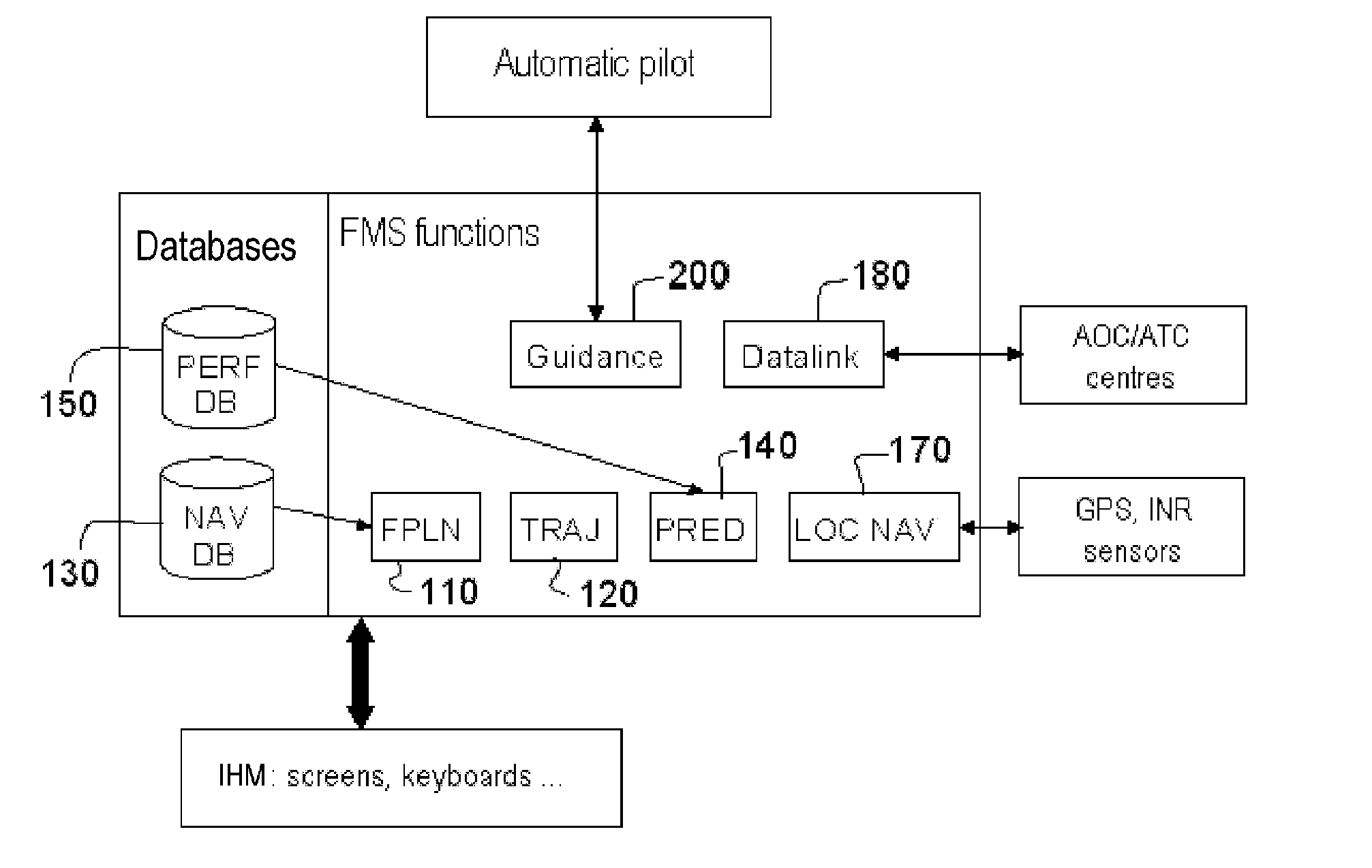
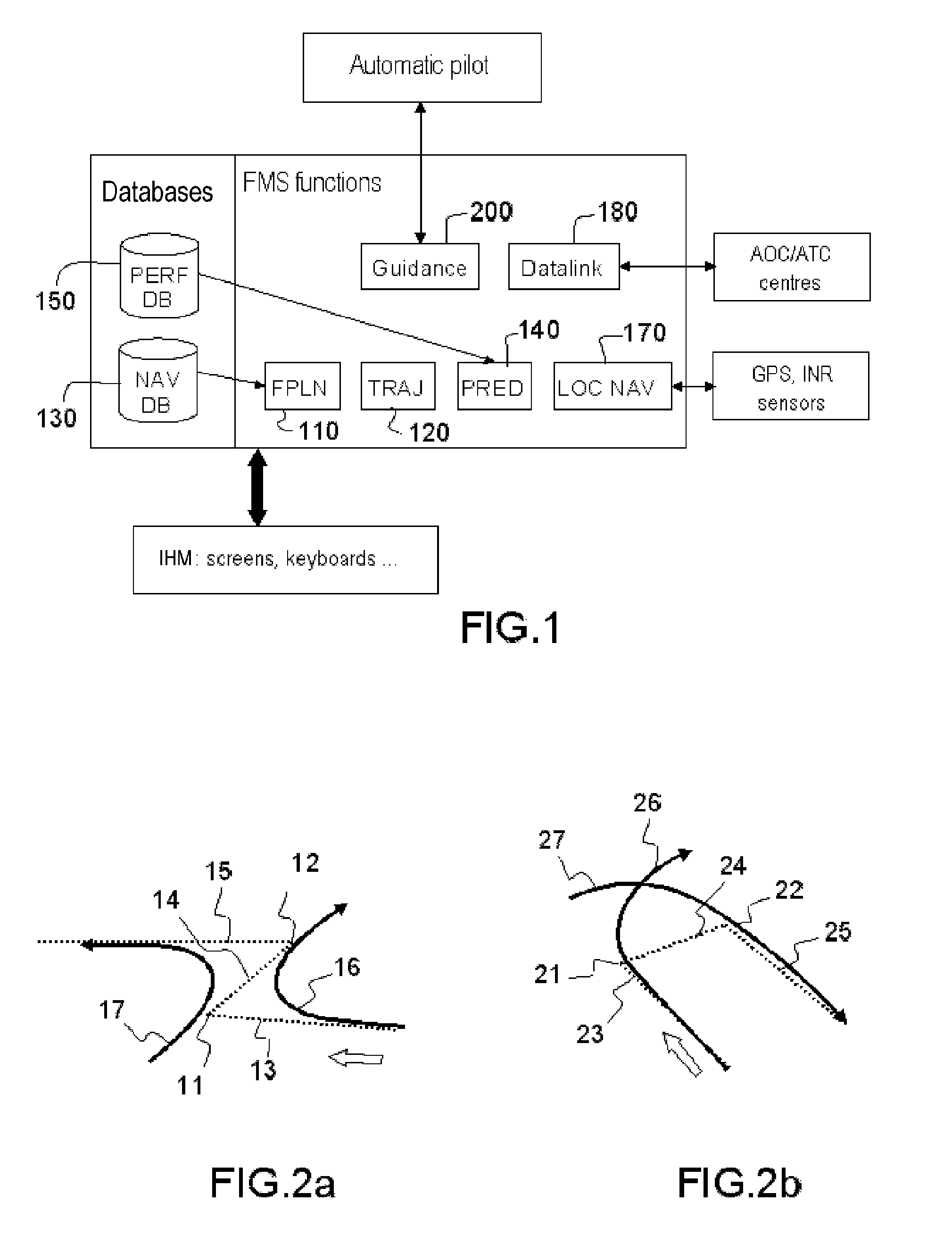
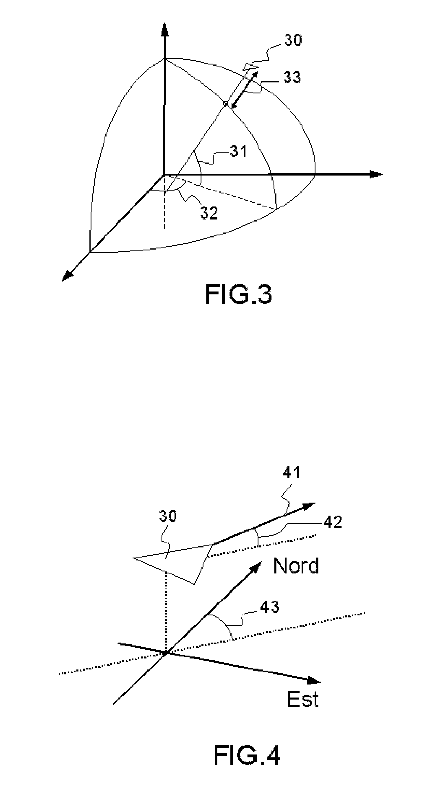
[0041]The present invention models a trajectory of an aircraft, not in geometric form, by its position coordinates, as is the case in the known FMS systems, but in the form of a sequence of state vectors Ei describing the evolution of a moving craft over time.

[0042]The time is the basis of the sequencement of this state vector. In a possible embodiment of the method, the time is used independently of the state vector; it constitutes a reference towards a state vector instance which is not itself dated. In another embodiment of the method, the time is integrated into the state vector, the list of state vector ordered by their temporal component constituting the trajectory of the aircraft. This second embodiment turns out to be particularly advantageous in the case where a variable time interval between two instances of the state vector is envisaged. These two approaches for indexing the time can be envisaged for the method according to the invention.

[0043]Moreover, the time can be ex...


PUM


Abstract

A method for constructing a flight trajectory of an aircraft, comprises a step of computing a sequence of state vectors (Ei) representing the trajectory of the aircraft; a state vector (Ei+1) being determined on the basis of the state vector (Ei) preceding it by means of: a step of computing the speed components (Vi+1), consisting in determining: a flight setpoint, by selecting an objective navigation point, a joining strategy adapted to the flight setpoint and to the flight domain (DV) by means of a predefined library (LSr) of joining strategies, a manoeuvre by means of the flight domain (DV), making it possible to follow the joining strategy towards the flight setpoint; a step of computing the other components of the state vector (Ei+1), on the basis of the components of the speed vector (Vi+1) and of the preceding state vector (Ei).

Description

CROSS-REFERENCE TO RELATED APPLICATION[0001]This application claims priority to foreign French patent application No. FR 1202124, filed on Jul. 27, 2012, the disclosure of which is incorporated by reference in its entirety.FIELD OF THE INVENTION[0002]The invention relates to a flight management method for the construction of a trajectory of an aircraft, by means of a sequence of state vectors indexed with respect to time, and to a trajectory computation method implementing this vector representation. It also pertains to the computation of the transitions between the various elements of a flight plan as a function of the aircraft's flight domain as well as the estimations in terms of time and fuel relating to this trajectory.BACKGROUND[0003]Flight management systems, commonly referred to by the acronym FMS, have in their main jobs to provide the crew with a strategic overview of their flight, this including for example the construction of a trajectory between waypoints or a precise d...

Claims


Application Information

Patent Timeline
IPC IPC(8): G01C21/00
CPCG01C21/00G01C23/00G05D1/101G08G5/0034G08G5/0039
Inventor COURTEVILLE, ROMAINBARNETCHE, BERTRAND
Owner THALES SA
Learn More