
Automatic Scene Modeling for the 3D Camera and 3D Video

a technology of automatic scene modeling and 3d camera, applied in the field of image processing technology, can solve the problems of no ability to move around in the 3d, no depth perception, no ability to incorporate foreground objects, etc., and achieve the effect of reducing video bandwidth and high frame-ra

Inactive Publication Date: 2008-10-09
SUMMERS
View PDF12 Cites 396 Cited by
  • Summary
  • Abstract
  • Description
  • Claims
  • Application Information

AI Technical Summary

Benefits of technology

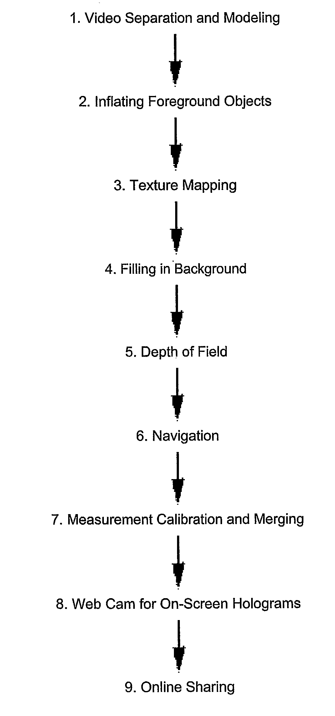
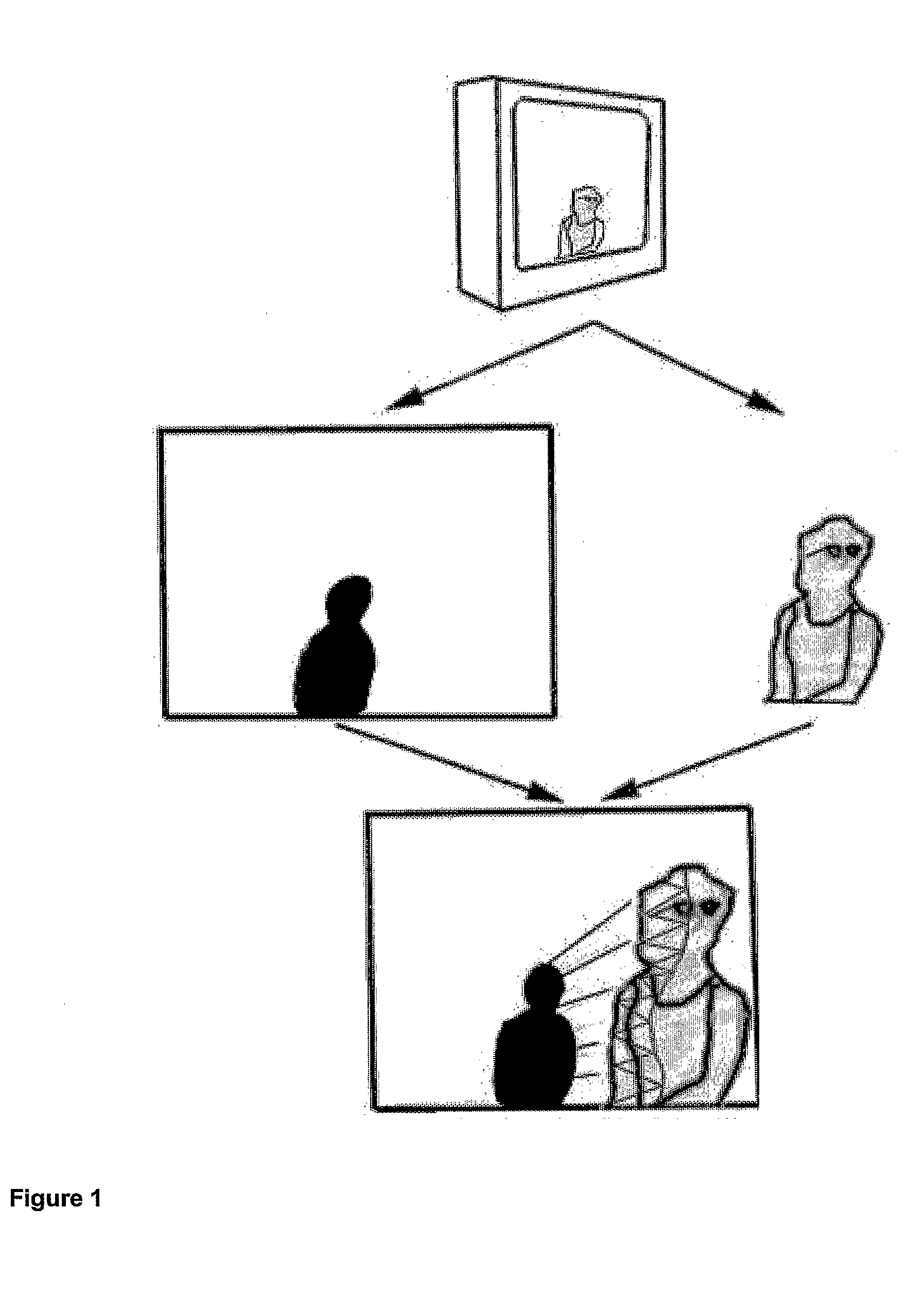
[0019]The image-processing technology described in the present invention is illustrated in FIG. 1. It makes a balance of what is practical with achieving 3D effects in video that satisfy the eye with a rich 3D, moving, audio-visual environment. Motion parallax is used to add depth (Z) to each XY coordinate point in the frame, to produce single-camera automatic scene modeling for 3D video. While designed to be convenient since it is automatic and cost effective for consumers to use, it also opens up an entire new interface for what we traditionally think of as motion pictures, in which the movie can move, but the viewing audience can move as well. Movies could be produced anticipating navigation within and between scenes. But even without production changes, software for set-top boxes and computers could allow any video signal to be geometrically rendered with this system.
[0034]As well as opening up new possibilities for producers and users of interactive television, the ability to separate foreground objects contributes to the ability to transmit higher frame-rates for moving than static objects in compression formats such as MPEG-4, to reduce video bandwidth.

Problems solved by technology

Unfortunately, these approaches are based on nodal panoramas constrained to one viewpoint for simple operation.
But even though a 3D model underlies the scene in each case, there is no ability to move around in the 3D model, no ability to incorporate foreground objects, and no depth perception from parallax while foreground objects move relative to the background.
The limitations get worse with 360-degree video.
Even with the most expensive, high resolution cameras that are made, the resolution in video is inadequate for panoramic scenes.
However, this is ordinarily a time-consuming approach that requires expensive computer hardware and software and extensive training.
Yet creating point clouds by hand one point at a time is obviously slow.
While realistic shapes can be manually created for manufactured objects, this also does not work well for soft gradients and contours on organic objects.
Although Bracey et al. say that this could be done manually or with a computer program, recognizing something that has a different shape from different views is a fundamental problem of artificial intelligence that has not been solved computationally.
Specialized hardware systems also exist for generating 3D geometry from real-life objects, although all tend to be labor-intensive and require very expensive equipment:Stereo Vision: Specialized industrial cameras exist with two lens systems calibrated a certain distance apart.
These are not for consumer use, and would have extra costs to manufacture.
This approach requires expensive equipment, is based on massive data sets, is slow and is not photorealistic.
These setups involve substantial costs and inconvenience with specialized hardware, and tend to be suited to small objects, rather than objects like a building or a mountain range.
There are also no accessible tools for converting from XYZ points to a 3D surface model.
There is no system on the market that lets people navigate on their own through moving video—whether for professionals or at consumer levels.
There is also no system available that generates a geometric model from video automatically.
There is also no system that works on photos or video, and no system that will automatically generate a geometric model from just a few images automatically without manual marking of matching targets in comparison pictures.
Finally, specialized approaches such as laser range finding, stereoscopy, various forms of 3D rendering and photogrammetry have steep equipment, labor and training costs, putting the technology out of range for consumers and most film-makers outside a few major Hollywood studios.

Method used


Image

  • Automatic Scene Modeling for the 3D Camera and 3D Video
  • Automatic Scene Modeling for the 3D Camera and 3D Video
  • Automatic Scene Modeling for the 3D Camera and 3D Video

Examples


Embodiment Construction

[0043]A better viewing experience would occur with photos and video if depth geometry was analyzed in the image processing along with the traditional features of paintings and images, such as color and contrast. Rather than expressing points of color on a two-dimensional image as in a photo, a painting or even in cave drawings, the technology disclosed here processes 3D scene structure. It does so from ordinary digital imaging devices, whether still or video cameras. The processing could occur in the camera, but ordinarily will happen with the navigation at the viewer. This processing occurs automatically, without manual intervention. It even works with historic movie footage.

[0044]Typically in video there will be scene changes and camera moves that will affect the 3D structure. Overall optical flow can be used as an indicator of certain types of camera movement; for example, swiveling of the camera around the lens' nodal point would remove parallax and cause flattening of the 3D mo...


PUM


Abstract

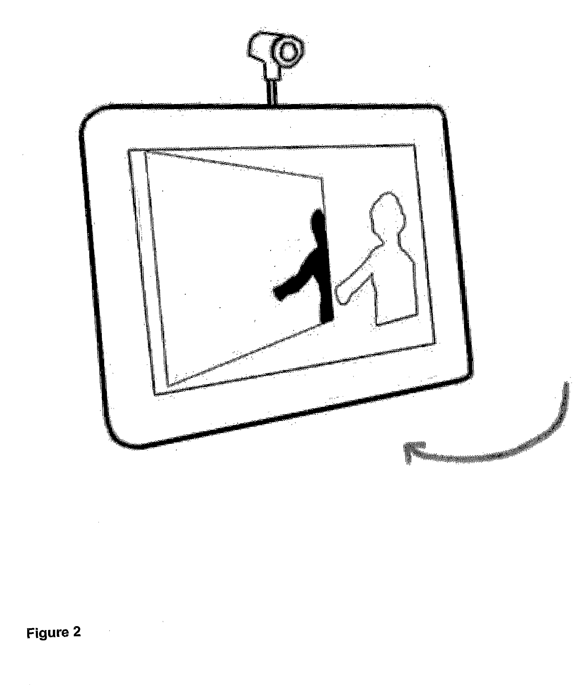
Single-camera image processing methods are disclosed for 3D navigation within ordinary moving video. Along with color and brightness, XYZ coordinates can be defined for every pixel. The resulting geometric models can be used to obtain measurements from digital images, as an alternative to on-site surveying and equipment such as laser range-finders. Motion parallax is used to separate foreground objects from the background. This provides a convenient method for placing video elements within different backgrounds, for product placement, and for merging video elements with computer-aided design (CAD) models and point clouds from other sources. If home users can save video fly-throughs or specific 3D elements from video, this method provides an opportunity for proactive, branded media sharing. When this image processing is used with a videoconferencing camera, the user's movements can automatically control the viewpoint, creating 3D hologram effects on ordinary televisions and computer screens.

Description

FIELD OF INVENTION[0001]This invention is directed to image-processing technology and, in particular, the invention is directed to a system and method that automatically segments image sequences into navigable 3D scenes.BACKGROUND OF THE INVENTION[0002]Virtual tours have to this point been the biggest application of digital images to 3D navigation. There are a number of photo-VR methods, from stitching photos into panoramas to off-the-shelf systems that convert two fisheye shots into a spherical image, to parabolic mirror systems that capture and unwarp a 360-degree view. Unfortunately, these approaches are based on nodal panoramas constrained to one viewpoint for simple operation. They all allow on-screen panning to look around in a scene and zooming in until the image pixellates. But even though a 3D model underlies the scene in each case, there is no ability to move around in the 3D model, no ability to incorporate foreground objects, and no depth perception from parallax while f...

Claims


Application Information

Patent Timeline
Patent Type & Authority Applications(United States)
IPC IPC(8): G06T17/00G06T17/20G06T15/00G06T7/20G06T5/00A63F13/00H04N13/02H04N5/262G06V10/26
CPCG06F3/0304G06F3/04815G06K9/34G06T7/0071G06T17/00G06T7/579G06V10/26A63F13/50
Inventor SUMMERS
Owner SUMMERS
Learn More