Ultrasonic transducer and ultrasonic flow-meter

a transducer and ultrasonic technology, applied in the direction of volume/mass flow measurement, measurement devices, instruments, etc., can solve the problems of adverse effects on measurement accuracy and propagation time, and achieve accurate setting, accurate measurement of flow rate, and accurate setting

Active Publication Date: 2014-02-06
PANASONIC INTELLECTUAL PROPERTY MANAGEMENT CO LTD
View PDF2 Cites 28 Cited by
  • Summary
  • Abstract
  • Description
  • Claims
  • Application Information

AI Technical Summary

Benefits of technology

[0021]Consequently, the position and inclination of the ultrasonic wave radiation surface of the ultrasonic wave transmitting and receiving unit can be accurately set, thus accurately measuring the flow rate.
[0022]As described above, with the ultrasonic wave transmitting and receiving unit and the ultrasonic wave flow rate measuring apparatus according to the present invention, the ultrasonic wave radiation surface can be accurately set, thus accurately measuring the flow rate.

Problems solved by technology

In this case, there arises a problem to be solved that a propagation time, that is, measurement accuracy is adversely affected.
However, there remains a problem to be solved with respect to a method for fixing unit 120 such configured as described above to a channel with little reverberant propagation.PTL 1: Unexamined Japanese Patent Publication No. 2001-159551PTL 2: Unexamined Japanese Patent Publication No.

Method used


Image

  • Ultrasonic transducer and ultrasonic flow-meter
  • Ultrasonic transducer and ultrasonic flow-meter
  • Ultrasonic transducer and ultrasonic flow-meter

Examples


first exemplary embodiment

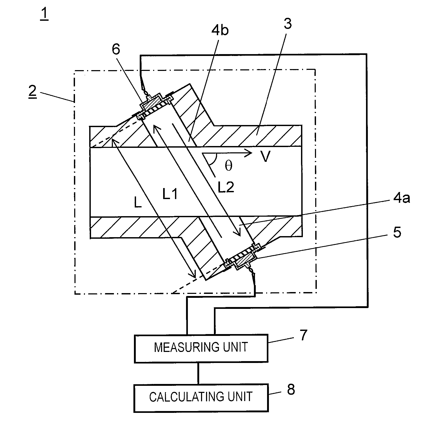
[0039]FIG. 1 is a cross-sectional view showing ultrasonic flow rate measuring apparatus 1 in a first exemplary embodiment according to the present invention.

[0040]As shown in FIG. 1, flow rate measuring unit 2 in ultrasonic flow rate measuring apparatus 1 is provided with channel 3.

[0041]Openings 4a and 4b for propagating ultrasonic waves so as to transmit and receive them are formed in a slantwise direction with respect to channel 3. Ultrasonic wave transmitting and receiving units 5 and 6 are fixed to the ends of openings 4a and 4b, respectively, in such a manner as to face each other.

[0042]Referring to FIG. 1, reference character L1 designates a propagation channel for an ultrasonic wave that is propagated from ultrasonic wave transmitting and receiving unit 5 whereas reference character L2 designates a propagation channel for an ultrasonic wave that is propagated from ultrasonic wave transmitting and receiving unit 6.

[0043]Here, a flow rate of a fluid flowing in channel 3 is rep...

second exemplary embodiment

[0072]Next, a description will be given of a second exemplary embodiment according to the present invention.

[0073]FIG. 6 is a cross-sectional view showing the configuration of ultrasonic wave transmitting and receiving unit 5 and the configuration of a portion which is fixed to channel 3 in the second exemplary embodiment according to the present invention. Moreover, FIG. 7 is a cross-sectional view showing region Q shown in FIG. 6 in enlargement. FIG. 8 is a cross-sectional view taken along line 8-8 of FIG. 6.

[0074]As shown in FIG. 6, the present exemplary embodiment is identical to the first exemplary embodiment in that ultrasonic wave transmitting and receiving unit 5 covered with insulating vibration suppressing member 20 is fixed at opening 4a formed in channel 3 by fixing member 21 in such a manner as to be pressed against channel 3.

[0075]Referring to FIG. 7, region Q shown in FIG. 6 will be explained in detail. Insulating vibration suppressing member 20 has holes 22 that are ...

third exemplary embodiment

[0082]Next, a description will be given of a third exemplary embodiment according to the present invention.

[0083]FIG. 10 is a cross-sectional view showing the configuration of ultrasonic wave transmitting and receiving unit 24 and the configuration of a portion which is fixed to channel 3 in a third exemplary embodiment according to the present invention.

[0084]Referring to FIG. 10, ultrasonic wave transmitting and receiving unit 24 is fixed at opening 4a formed in channel 3 by fixing member 9 in such a manner as to be pressed against channel 3.

[0085]In ultrasonic wave transmitting and receiving unit 24 in the present exemplary embodiment, piezoelectric member supporting plate 11 in ultrasonic wave transmitting and receiving unit 5 described in the first exemplary embodiment is replaced with topped cylindrical metal case 25.

[0086]Topped cylindrical metal case 25 is provided with top 26, side wall 27, and supporter 28 extending outward from side wall 27. Piezoelectric member 12 is joi...


PUM


Abstract

An ultrasonic wave transmitting and receiving unit includes: a piezoelectric member supporting plate; an acoustic matching member fixed to one surface of the piezoelectric member supporting plate; a piezoelectric member fixed to the other surface. Moreover, the ultrasonic wave transmitting and receiving unit includes: an insulating vibration suppressing member integrally formed in such a manner as to cover the piezoelectric member and the piezoelectric member supporting plate, wherein the insulating vibration suppressing member has a hole reaching the piezoelectric member supporting plate.

Description

TECHNICAL FIELD[0001]The present invention relates to an ultrasonic wave transmitting and receiving unit for transmitting an ultrasonic wave into a fluid or receiving an ultrasonic wave from a fluid, and an ultrasonic flow rate measuring apparatus using the ultrasonic wave transmitting and receiving unit.BACKGROUND ART[0002]Explanation will be made on the configuration of a conventional ultrasonic wave transmitting and receiving unit for use in an ultrasonic flow rate measuring apparatus.[0003]FIG. 11 is a cross-sectional view showing the configuration of a conventional ultrasonic wave transmitting and receiving unit.[0004]In an embodiment shown in FIG. 11, ultrasonic wave transmitting and receiving unit 100 is provided with top 60, side wall 61, case 63, piezoelectric member 64, vibration suppressor 65, holder 66, and vibration transmission suppressor 67.[0005]Case 63 is formed into a topped cylindrical shape, and has side wall 61 and supporter 62 extending outward from side wall 6...

Claims


Application Information

Patent Timeline
Patent Type & Authority Applications(United States)
IPC IPC(8): G01F1/66
CPCG01F1/66G01F1/662G01F1/667G10K11/002
Inventor SATOU, MASATOMORIHANA, HIDEAKIADACHI, AKIHISANAKANO, MAKOTOOZAKI, YUKINORI
Owner PANASONIC INTELLECTUAL PROPERTY MANAGEMENT CO LTD
Why Eureka
Try Eureka