Assembly for use in a crankcase ventilation system, a crankcase ventilation system comprising such an assembly, and a method for installing such an assembly

a technology for ventilation systems and crankcases, which is applied in the direction of engine components, machines/engines, non-fuel substance addition to fuel, etc., can solve the problem that gases and/or vapors cannot accumulate in at least part of the air intake system

Inactive Publication Date: 2014-02-06
VIALLE GRP
View PDF11 Cites 6 Cited by
  • Summary
  • Abstract
  • Description
  • Claims
  • Application Information

AI Technical Summary

Benefits of technology

[0009]It is a first object of the present invention to provide an improved assembly for use in a crankcase ventilation system of an internal combustion engine. In an embodiment the assembly improves starting of such an engine in such a way that it starts substantially at the first attempt, particularly after it has been shut down for a long period of time as mentioned above. It is a second object of the present invention to provide a crankcase ventilation system that comprises such an assembly. It is a third object of the present invention to provide an internal combustion engine comprising a crankcase ventilation system as mentioned above. It is a fourth object of the present invention to provide a vehicle comprising an internal combustion engine as mentioned above. It is a fifth object of the present invention to provide a method for providing an assembly according to the invention in a crankcase ventilation system of an internal combustion engine.
[0010]At least one of these objects is achieved by an assembly comprising a shutter arrangement that is constructed and arranged for preventing that residual gases and / or vapors out of a crankcase flow into an air intake system for the cylinder during a period of time that starts at shut down of the engine and ends after it has been re-started, and an outlet that is constructed and arranged for removing at least a substantial part of the residual gases and / or vapors from the engine as long as it is shut down. Contrary to the control valve of the crankcase ventilation system, the shutter arrangement of the assembly according to the present invention is constructed and arranged to move towards a closed position when the engine is shut down and remains closed until after the engine has been re-started. In this way, the shutter arrangement prevents that residual gases and / or vapors out of a crankcase flow into the air intake duct of the air intake system as long as the engine is shut down and upon re-starting of the engine because of the considerable under pressure that is generated in the purge duct upon cranking. At least a substantial part of the residual gases and / or vapors out of a crankcase can escape from the engine, e.g. towards the outside environment, via the outlet of the assembly according to the present invention. The residual gases and / or vapors that still might be present in a crankcase even after the engine has been shut down for a long time, e.g. 12 hours or more, will not be drawn into the air intake duct upon re-starting of the engine. In this way, it is prevented that the mixture that is drawn into the combustion chambers during cranking is over-rich due to residual gases and / or vapors out of a crankcase. As a result, the engine should start at the first attempt even when the engine has been shut down for a long period of time, e.g. 12 hours or more.
[0011]In an embodiment of the assembly according to the present invention, the internal combustion engine is a liquefied gas powered direct injection engine. Especially in the case of engines that are powered by a liquefied gas, e.g. propane, butane or a mixture thereof, it is important to prevent the supply of an over-rich mixture to the combustion chambers at the first attempt of starting the engine when it has been shut down for a long period of time as mentioned above.

Problems solved by technology

As a result, these gases and / or vapors cannot accumulate in at least part of the air intake system as long as the engine is down.

Method used


Image

  • Assembly for use in a crankcase ventilation system, a crankcase ventilation system comprising such an assembly, and a method for installing such an assembly
  • Assembly for use in a crankcase ventilation system, a crankcase ventilation system comprising such an assembly, and a method for installing such an assembly
  • Assembly for use in a crankcase ventilation system, a crankcase ventilation system comprising such an assembly, and a method for installing such an assembly

Examples


Embodiment Construction

[0034]The figures are not necessarily drawn to scale. Identical components in the figures are denoted by the same reference numerals.

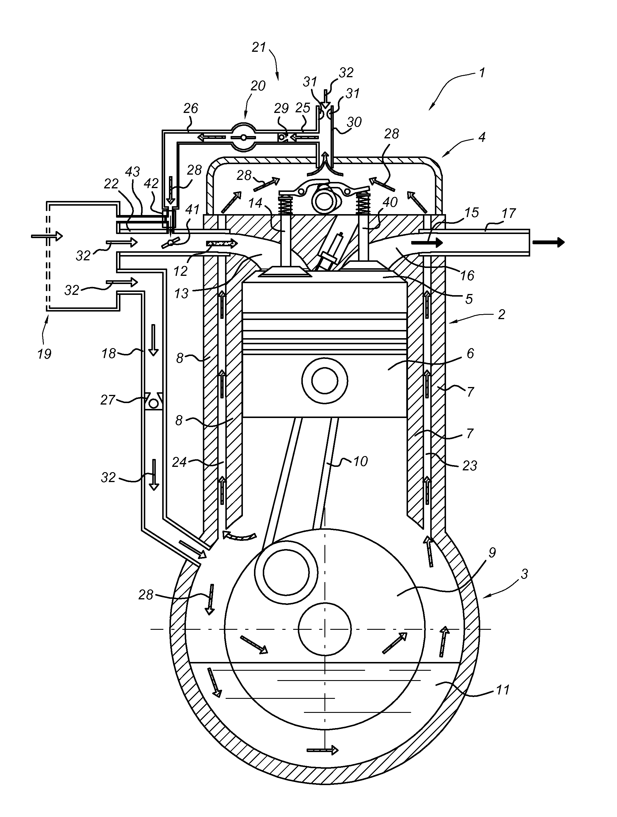
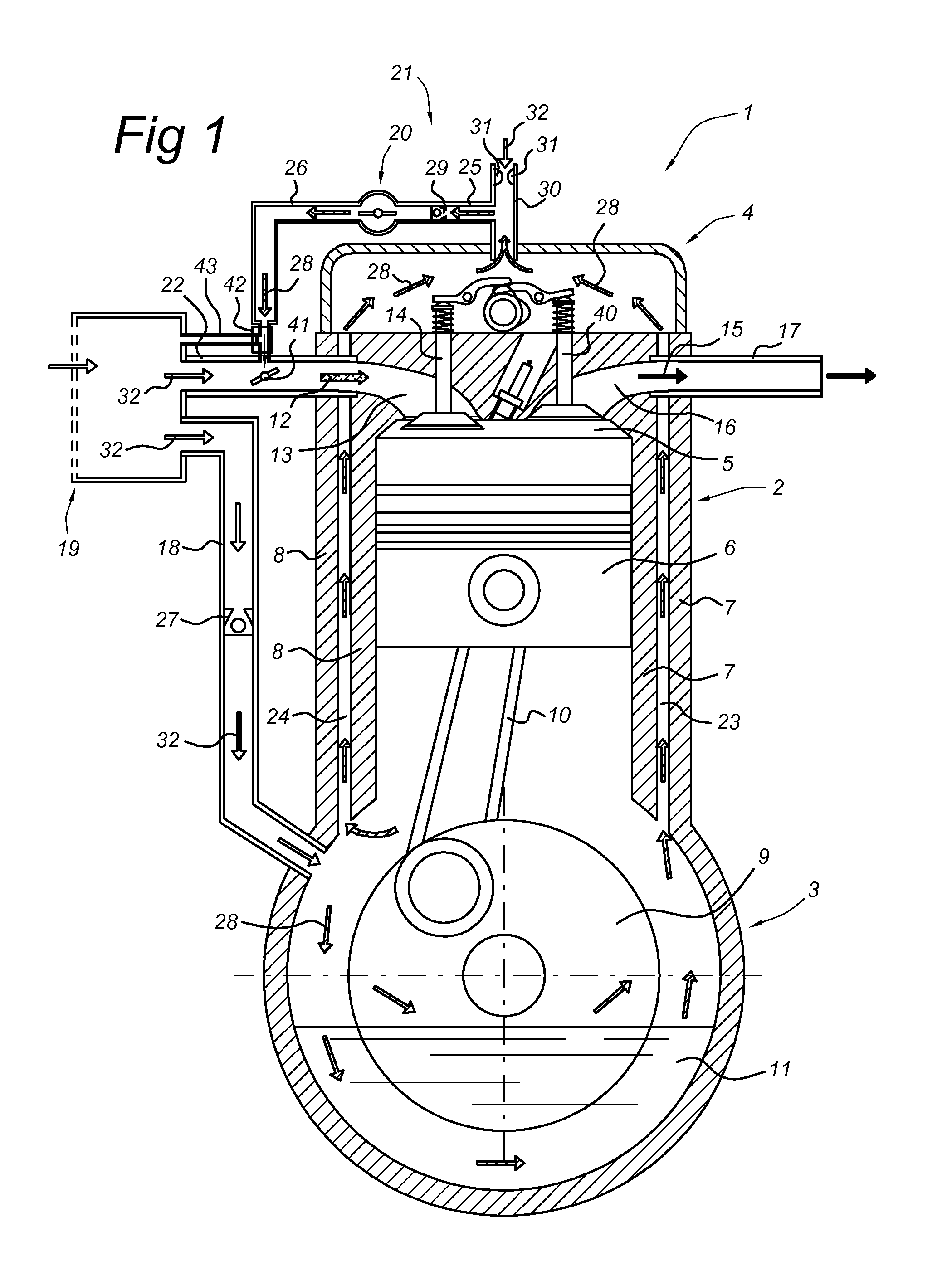
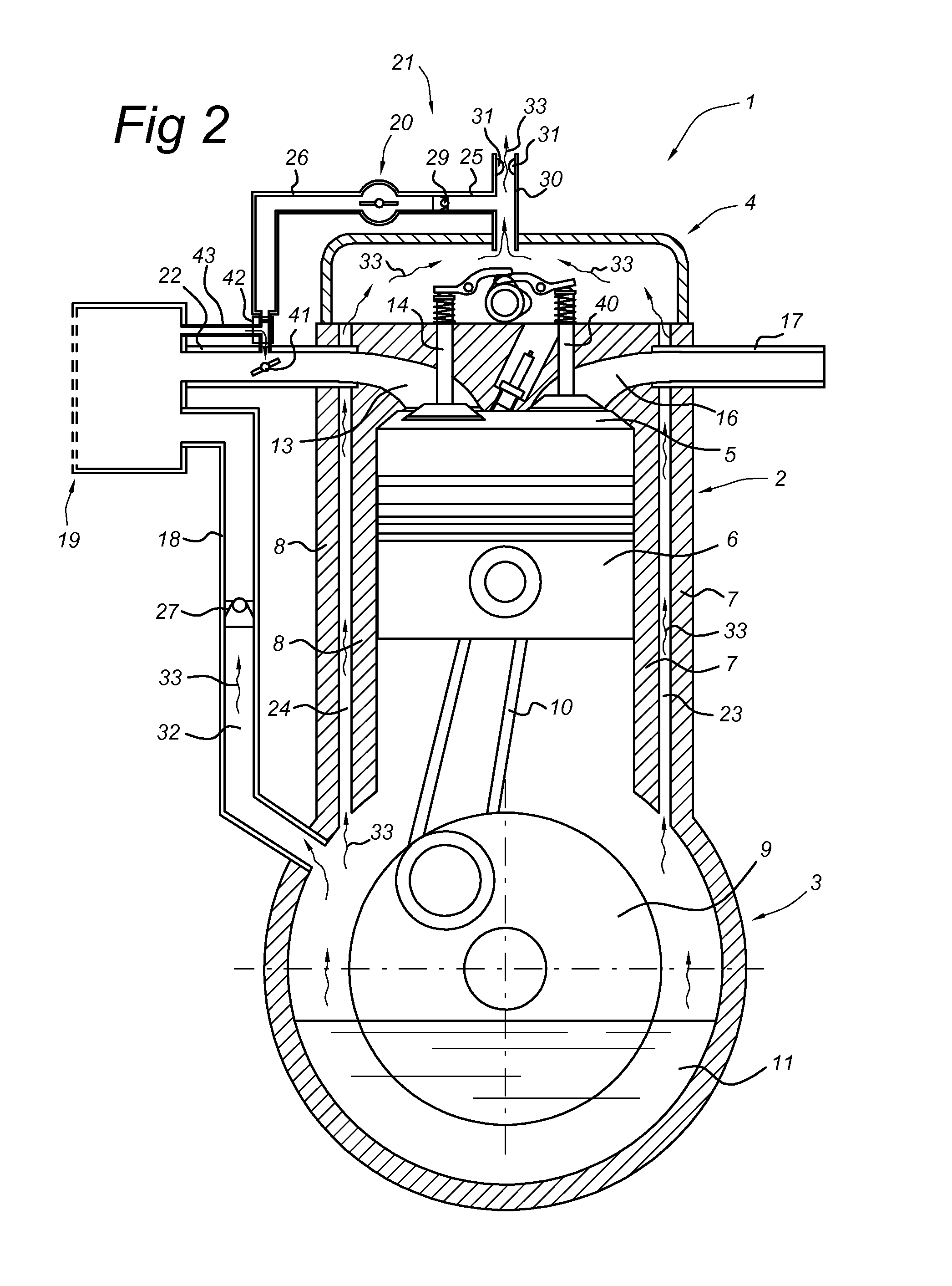
[0035]FIG. 1 shows a schematic cross section of part of an internal combustion engine 1 comprising a cylinder 2 that is connected at its lower end to a crankcase 3 and at its upper end to a valve cover 4. Various flows of gases and / or vapors are schematically indicated in the case that the engine is running. The cylinder 2 comprises a combustion chamber 5 having a piston 6 that is constructed and arranged for being movable inside the combustion chamber 5 while being in sliding contact with the walls 7, 8 of the cylinder 2. The piston 6 is connected to a crankshaft 9 via a connecting element 10. The crankshaft 9 is supplied with a lubricant 11, e.g. oil, for smooth operation and / or cooling and to prevent wear.

[0036]A mixture 12 comprising air 32 and / or fuel can enter the combustion chamber 5 via an intake manifold 13 that can be closed by an inlet valve...


PUM

PropertyMeasurementUnit
opening pressureaaaaaaaaaa
of timeaaaaaaaaaa
timeaaaaaaaaaa

Abstract

An assembly for use in a crankcase ventilation system of an internal combustion engine includes a shutter arrangement that is constructed and arranged for preventing that residual gases and / or vapors out of a crankcase flow into an air intake system during a period of time that starts at shut down of the engine and ends after it has been re-started. The assembly also includes an outlet that is constructed and arranged for removing at least a substantial part of the residual gases and / or vapors from the engine as long as it is shut down.

Description

CROSS REFERENCE TO RELATED APPLICATIONS[0001]This application is a continuation of PCT application number PCT / NL2012 / 050236 filed on 10 Apr. 2012, which claims priority from Netherlands application number 2006586 filed on 11 Apr. 2011. Both applications are hereby incorporated by reference in their entireties.BACKGROUND OF THE INVENTION[0002]1. Field of the Invention[0003]The present invention relates to an assembly for use in a crankcase ventilation system of an internal combustion engine with at least one cylinder having a piston and a combustion chamber. The present invention also relates to a crankcase ventilation system for use in an internal combustion engine, wherein the crankcase ventilation system comprises such an assembly. The present invention further relates to an internal combustion engine comprising a crankcase ventilation system as mentioned above. The present invention also relates to a vehicle comprising an internal combustion engine as mentioned above. The present...

Claims


Application Information

Patent Timeline
Patent Type & Authority Applications(United States)
IPC IPC(8): F02M25/06
CPCF02M25/06F01M13/022F01M13/023F01M13/025Y10T29/49231F01M13/00F01M13/02
Inventor JAASMA, SERVATIUS ALFONS MARIA
Owner VIALLE GRP
Why Eureka
Try Eureka