Shadow Band Pyranometer with Shadow Band Support

a technology of shadow band and pyranometer, which is applied in the field of shadow band pyranometer, can solve the problems of expensive and complicated apparatus, and achieve the effect of convenient cleaning

Active Publication Date: 2014-02-06
ACCUFLUX
View PDF5 Cites 3 Cited by
  • Summary
  • Abstract
  • Description
  • Claims
  • Application Information

AI Technical Summary

Benefits of technology

[0009]It will be appreciated that the shadow arm of the present invention does not need to be adjusted to compensate for the changing declination of the sun. Moreover, the shadow arm of the invention does not cast any shadow on the second sun sensor. Furthermore, the location of the cleaning nozzle allows the first sun sensor to be easily cleaned by injecting cleaning fluid through the nozzle down onto the first sun sensor.

Problems solved by technology

However, the apparatus is extremely complicated and costly.

Method used


Image

  • Shadow Band Pyranometer with Shadow Band Support
  • Shadow Band Pyranometer with Shadow Band Support
  • Shadow Band Pyranometer with Shadow Band Support

Examples


Embodiment Construction

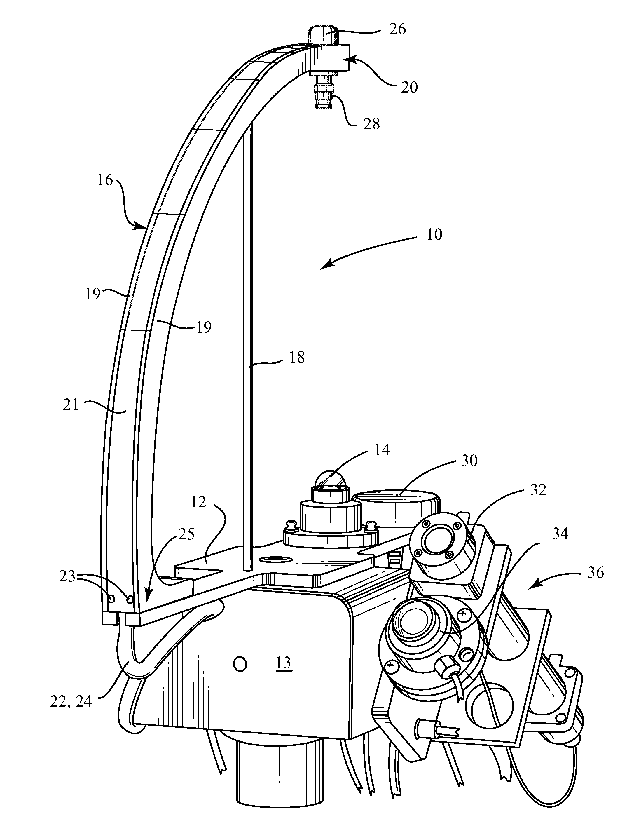
[0027]Turning now to FIG. 3, a shadow band pyranometer 10 according to the present invention includes a motor driven platform 12 having a centrally located sun sensor 14. The platform 12 is mounted on a motor drive unit 13 and is preferably arranged to be parallel to the ground on which the pyranometer rests. A generally vertical and arcuate shade arm (shadow band) 16 extends upward from and substantially perpendicular to the platform 12 at a distance away from the sensor 14. The arm 16 traverses an arc of approximately 90 degrees (preferably 92.5 degrees) and terminates approximately directly above the sensor 14.

[0028]According to the presently preferred embodiment, a vertical stabilizer strut 18 supports the arm 16 close to its free end 20 to provide added rigidity to the structure, especially in areas where there are high winds. As seen best in FIG. 6, the arm 16 is advantageously hollow and includes a generally upwardly-opening U-shaped channel defined by the base 17 and sidewal...


PUM


Abstract

A shadow band assembly includes a platform and an arcuate shadow arm extending upward from the platform and terminating in a free end above the platform. A sun sensor mounting location is located below the free end of the shadow arm. The arm is preferably further supported by a vertical strut. According to other embodiments, the arm is hollow and contains a fluid conduit and / or an electrical cable. A sun sensor may be mounted on top of the free end of the arm and a fluid nozzle may be mounted under the free end. A shadow band pyranometer includes the shadow band assembly, a sun sensor mounted at the mounting location and a motor drive coupled to the platform for azimuth tracking Additional sensors with zenith tracking may also be provided.

Description

[0001]This application is a continuation of U.S. patent application Ser. No. 13 / 918,975 filed on Jun. 16, 2013, which is a continuation of U.S. patent application Ser. No. 12 / 706,919, filed on Feb. 17, 2010, now U.S. Pat. No. 8,481,905 issued on Jul. 9 2013. The entire contents of U.S. patent application Ser. No. 13 / 918,975 and U.S. patent application Ser. No. 12 / 706,919 are hereby incorporated by reference.FIELD OF INVENTION[0002]This invention relates broadly to pyranometers. More particularly, this invention relates to shadow band pyranometers for measuring diffuse solar radiation throughout the course of a day.STATE OF THE ART[0003]Pyranometers are a class of actinometers that measure the combined intensity of solar radiation. Pyranometers are used largely in research, particularly meteorological research. However, they are also used in agricultural and solar energy applications.[0004]A shadow band pyranometer is a conventional pyranometer to which a shadow band has been attache...

Claims


Application Information

Patent Timeline
Patent Type & Authority Applications(United States)
IPC IPC(8): G01S3/786F24J2/54F24S50/20
CPCF24J2/5417G01S3/7861G01J1/02G01J1/0271G01J1/4228G01J2001/4285F24S50/20F24S40/20F24S30/40F24S30/45Y02E10/47
Inventor DOLCE, ROBERT
Owner ACCUFLUX
Why Eureka
Try Eureka