
Wind park control system

a control system and wind park technology, applied in the control of electric generators, machines/engines, mechanical equipment, etc., can solve the problems of wind turbines giving more electrical loss than turbines, providing electrical loss to the overall system, etc., and achieve the effect of minimizing electrical losses and being efficient and reliabl

Inactive Publication Date: 2014-02-06
SIEMENS AG
View PDF7 Cites 10 Cited by
  • Summary
  • Abstract
  • Description
  • Claims
  • Application Information

AI Technical Summary

Benefits of technology

The patent text discusses a method for reducing electrical loss when connecting wind turbines to a wind park and utility grid. By selecting wind turbines that produce less electrical loss and provide more reactive power, the amount of reactive power provided by the wind turbines can be increased. This can be done by adding enough wind turbines to meet the requirements for reactive power in the utility grid. By doing this, wind turbines can contribute to the stability and reliability of the power system.

Problems solved by technology

All wind turbines provide electrical loss to the overall system, however, some wind turbines give more electrical loss than other.

Method used

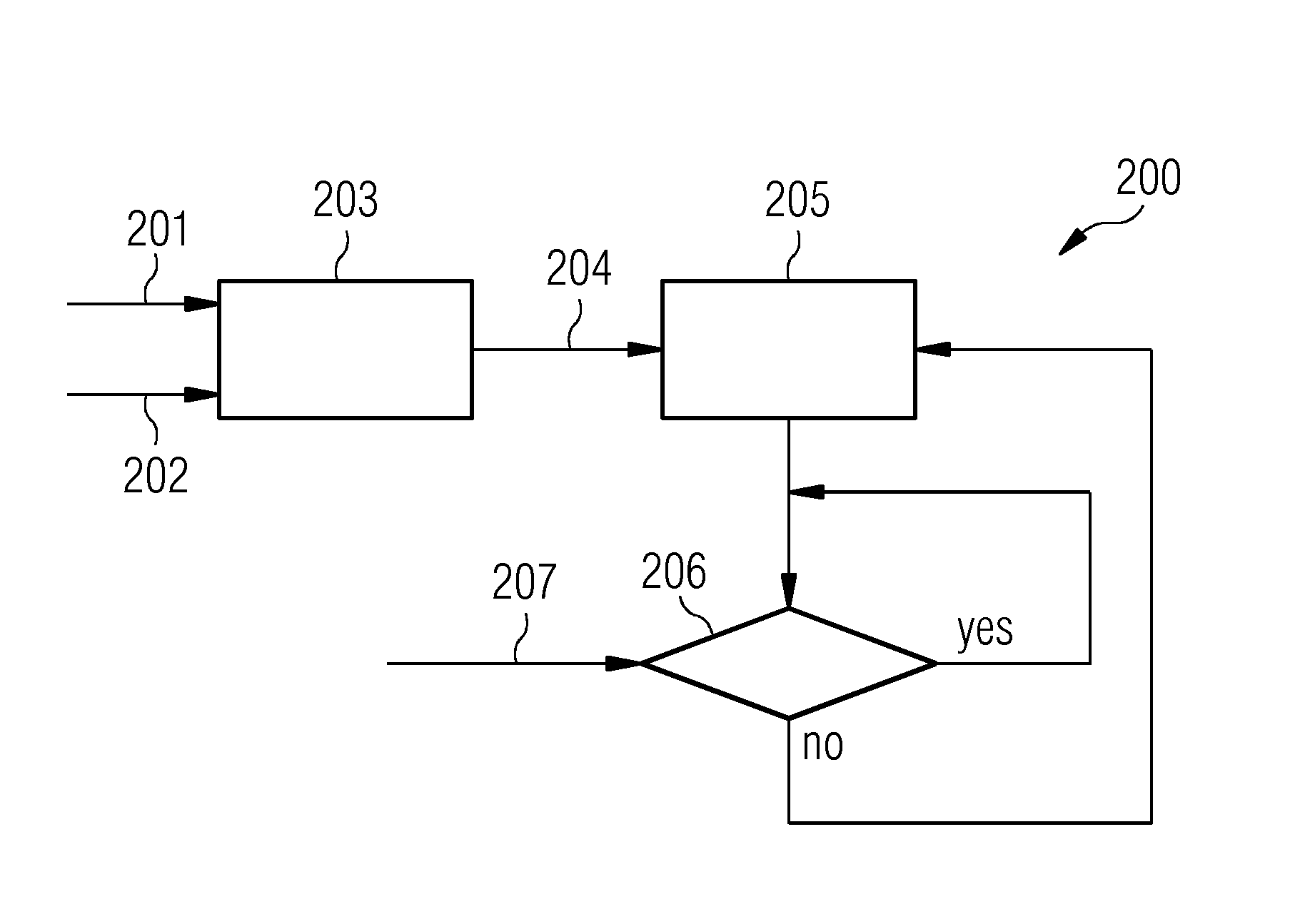

Image

  • Wind park control system
  • Wind park control system
  • Wind park control system

Examples


Embodiment Construction

[0038]The illustration in the drawing is schematically. It is noted that in different figures, similar or identical elements are provided with the same reference signs.

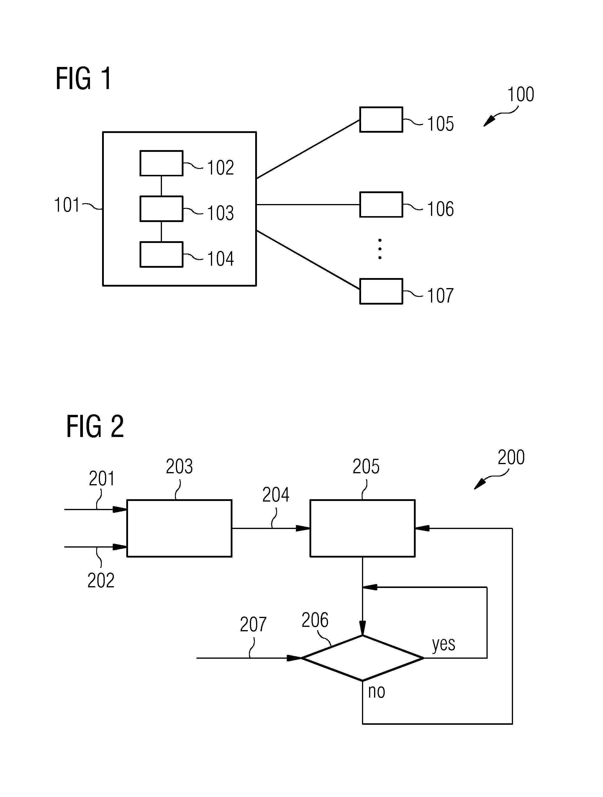
[0039]FIG. 1 shows a wind park 100. The wind park 100 comprises a wind park control system 101 and a plurality of wind turbines 105, 106, 107. The wind park control system is adapted to control a reactive power output of the plurality of wind turbines. The wind park may deliver active power and reactive power to a utility grid (not shown).

[0040]The wind park control system comprises a determination unit 102, a calculation unit 103 and an adjustment unit 104. The determination unit 102 is adapted to determine a total amount of reactive power being required by the utility grid. The determination unit is further adapted to determine for each wind turbine an individual amount of reactive power, which the wind turbine is capable to deliver.

[0041]The calculation unit 103 is adapted to calculate a capability scheme. The capa...


PUM


Abstract

A wind park control system for controlling reactive power output of wind turbines is described. The wind park delivers active power and reactive power to a utility grid. A total amount of reactive power required by the utility grid and an individual amount of reactive power for each wind turbine are determined. A capability scheme having an order for selecting the wind turbines to deliver reactive power is calculated based on the individual amount of reactive power and the total electrical power loss contributed by each connection of the wind turbines to the utility grid. An actual amount of reactive power provided by the wind turbines is adjusted. The reactive power output of each wind turbine is controlled based on the capability scheme. The wind turbines are selected for delivering reactive power in the order of the capability scheme so that the total amount of reactive power is fulfilled.

Description

CROSS REFERENCE TO RELATED APPLICATIONS[0001]The present application claims priority to European Patent Office application No. 12178689.1 EP filed Jul. 31, 2012, the entire content of which is hereby incorporated herein by reference.FIELD OF INVENTION[0002]The present invention relates to the technical field of wind parks. In particular, the present invention relates to a control system for a wind park, in particular controlling the reactive power output of each wind turbine in the wind park.BACKGROUND OF INVENTION[0003]Wind parks comprise a plurality of single wind turbines and provide power to a utility grid. Today utility grids require reactive power delivery / consumption from wind power plants or parks. The reactive power may be needed for instance by loads (like electrical motors). Modern wind turbines may be able to control their reactive power output. Thus, the reactive power requirement of the utility grid may be fulfilled.[0004]Typically, all wind turbines deliver or consume...

Claims


Application Information

Patent Timeline
IPC IPC(8): F03D9/00
CPCF03D9/005F03D7/0284H02J3/16H02J3/38F03D7/048F03D9/255F03D9/257Y02E10/72Y02E10/76Y02E40/30
Inventor BECH, JOHN
Owner SIEMENS AG
Learn More