Electrical Terminal

Inactive Publication Date: 2014-02-06
TYCO ELECTRONICS JAPAN GK
View PDF9 Cites 5 Cited by
  • Summary
  • Abstract
  • Description
  • Claims
  • Application Information

AI Technical Summary

Benefits of technology

The present invention aims to solve the problems of existing devices by providing a first member and a second member. The first member has a pair of connecting face portions, a coupling portion, and a plurality of serrations. The pair of connecting face portions face each other in a substantially V shape, with a gap between their inner faces gradually becoming smaller from the wider-gap side to the narrower-gap side. The coupling portion connects the pair of connecting face portions at the ends of the narrower-gap side of the inner faces. The plurality of serrations are disposed on the pair of inner faces and extend along intersecting directions. The second member has a substantially U shape that mates with the pair of connecting face portions and can displace the outer side faces of the pair of connecting face portions inward to urge the inner faces closer to each other. This design provides better stability and secure coupling of components.

Problems solved by technology

This makes it difficult to connect such a thin wire in a stable manner, especially when a single thin wire is connected.
Furthermore, the housing 210 is necessary in addition to the electrical terminal 220 to connect the wire 216, thereby posing a problem that the number of component parts is large.
However, the housing 310 is necessary in addition to the first and second terminals 320 and 330 to connect the wire 301, thereby posing a problem that the number of component parts is large.

Method used


Image

  • Electrical Terminal
  • Electrical Terminal
  • Electrical Terminal

Examples


Embodiment Construction

)

[0040]Hereinafter, embodiments of the present invention will be described with reference to the drawings.

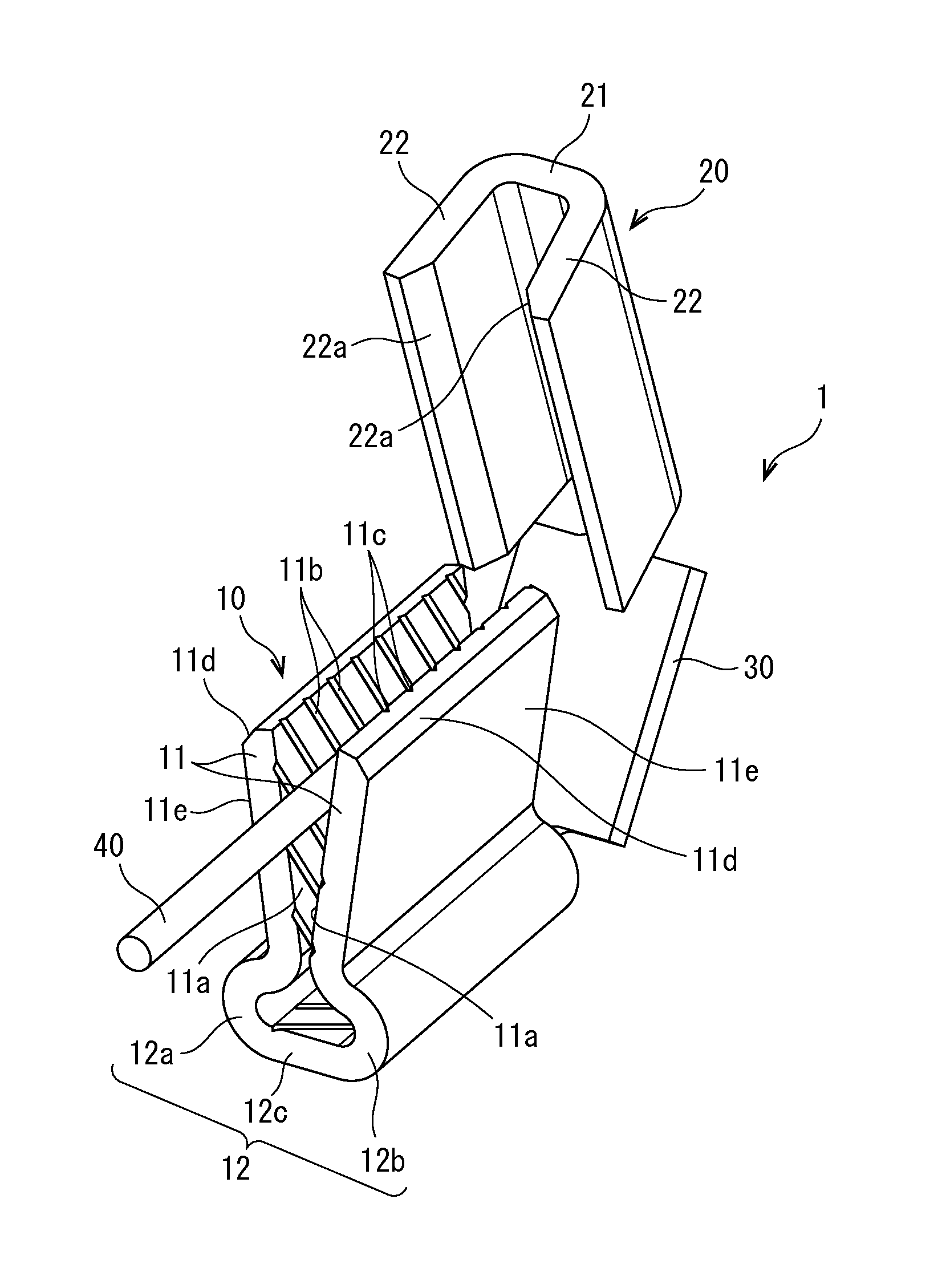
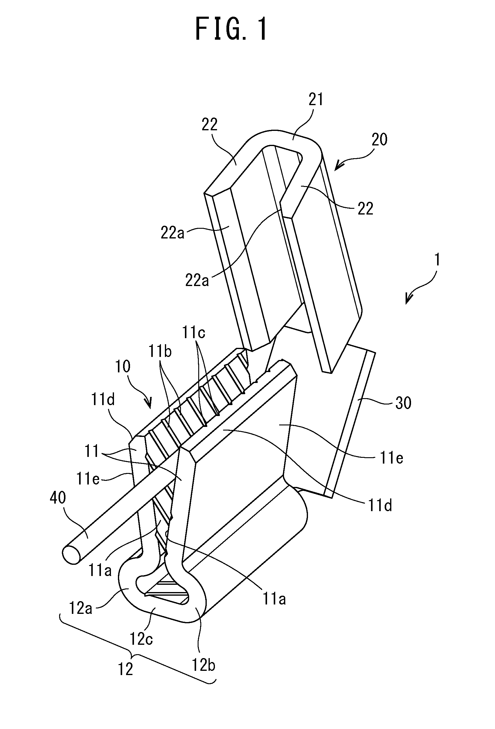
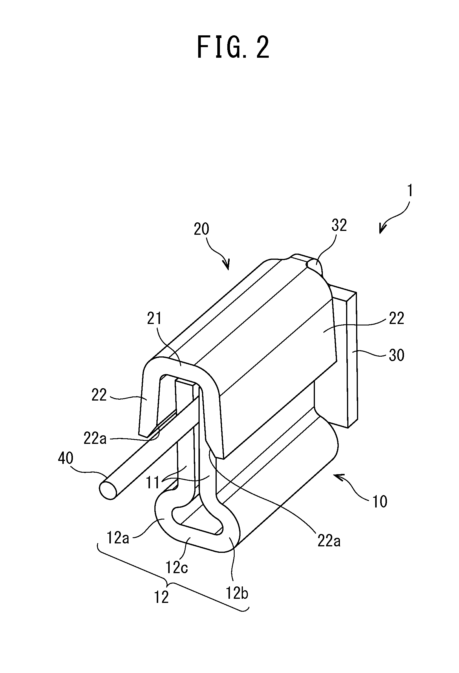
[0041]With reference to FIGS. 1 through 6, an electrical terminal 1 according to the invention will be described. A thin wire 40, such as a coil winding, is connected to the electrical terminal 1. The thin wire 40 is, for example, an electrical insulated wire having a metal core and an insulator covering the outer part of the metal core and having a diameter of approximately 0.02 mm to 0.25 mm, or a metal core having a diameter of approximately 0.02 mm to 0.25 mm. An example of the electrical insulated wire is a magnet wire. Hereinafter, an example of the magnet wire used as the wire 40 will be described.

[0042]The electrical terminal 1 shown in FIG. 1 to FIG. 6 is made by stamping and forming a metal sheet and includes a first member 10, a second member 20, and a coupling member 30 for coupling the first member 10 with the second member 20.

[0043]The first member 10 includes a pa...


PUM


Abstract

An electrical terminal is provided and includes a first member and a second member. The first member includes a pair of connecting face portions, a coupling portion, and a plurality of serrations. The pair of connecting face portions face each other in a substantially V shape such that a gap between inner faces of the pair of connecting face portions gradually becomes smaller from a wider-gap side to a narrower-gap side. The coupling portion connects the pair of connecting face portions at ends of the narrower-gap side of the inner faces. The plurality of serrations are disposed on the pair of inner faces and extend along intersecting directions. The second member has a substantially U shape that mates with the pair of connecting face portions and can displace outer side faces of the pair of connecting face portions inward to urge the inner faces closer to each other.

Description

CROSS-REFERENCE TO RELATED APPLICATIONS[0001]This application claims the benefit of the filing date under 35 U.S.C. §119(a)-(d) of Japanese Patent Application No. 2012-169949 of Jul. 31, 2012.FIELD OF THE INVENTION[0002]The present invention relates to an electrical terminal and, in particular, to an electrical connector for connection with a thin wire.BACKGROUND[0003]A known electrical terminal 101 for connection with a wire is disclosed in U.S. Pat. No. 4,003,623 B and shown in FIGS. 11 and 12.[0004]The known electrical terminal 101 shown in FIG. 11 includes a pair of side walls 104, 105 that extend from opposite sides of a base 103 and face each other. The shown embodiment is substantially U-shaped and includes a cavity 102 therein. The electrical terminal 101 is made by stamping and forming a metal sheet. The base 103 has an elongated shape for receiving wires W1 and W2 (see FIG. 12). A plurality of serrations 106 are successively positioned from the upper end of the one side wa...

Claims


Application Information

Patent Timeline
IPC IPC(8): H01R4/10
CPCH01R4/10H01R4/5008H01R4/5041H01R4/5075H01R13/62927H01R4/48H01R13/04
Inventor HARASAWA, MASAAKISAKAI, KEN
Owner TYCO ELECTRONICS JAPAN GK
Why Eureka
Try Eureka