Overload slip mechanism for the yaw drive assembly of a wind turbine

a wind turbine and drive assembly technology, applied in the direction of gearing details, machines/engines, gearing, etc., can solve the problems of affecting the operation of the wind turbin

Inactive Publication Date: 2014-02-13
GENERAL ELECTRIC CO
View PDF16 Cites 9 Cited by
  • Summary
  • Abstract
  • Description
  • Claims
  • Application Information

AI Technical Summary

Benefits of technology

[0009]In accordance with aspects of the invention, a yaw drive assembly for a wind turbine is provided. The assembly includes a drive motor having an output shaft. A reduction gear assembly having an input, such as an input shaft, is coupled to the output shaft of the drive motor. A drive gear, for example a pinion gear, is coupled to an output of the gear assembly and is configured for geared engagement with a yaw system bearing, which may be a geared inner or outer race of the bearing. A releasable and re-engageable coupling is operably configured between the drive gear and gear assembly output. The coupling is engaged and maintains a rotational drive engagement between the gear assembly output and the drive gear up to a defined rotational torque. This torque may be preset to correspond to the torque expected from an extreme load condition resulting from, for example, a severe wind event. At the defined rotational torque, the coupling disengages and isolates the gear assembly output from the drive gear. The coupling re-engages the gear assembly output to the drive gear upon the rotational torque decreasing to below the defined rotational torque.

Problems solved by technology

Generally, numerous yawing devices are required within each wind turbine to supply the force needed to yaw the wind turbine, especially under less-than-optimal weather conditions, i.e. in high winds.
The requirement to fully withstand these simulated loads and maintain, for example, a 20 year service life imparts significant costs into the yaw system design.
The combination of a high gear ratio (e.g., 10,000 to 1 in certain systems) coupled with a high inertial motor results in significant yaw system loads as the motor accelerates.
However, the challenges with this system are the increased costs associated with the motors, drives, drive transformers, drive controls, machine head cable twist during grid outages, standstill fatigue, and so forth.

Method used


Image

  • Overload slip mechanism for the yaw drive assembly of a wind turbine
  • Overload slip mechanism for the yaw drive assembly of a wind turbine
  • Overload slip mechanism for the yaw drive assembly of a wind turbine

Examples


Embodiment Construction

[0022]Reference now will be made in detail to embodiments of the invention, one or more examples of which are illustrated in the drawings. Each example is provided by way of explanation of the invention, not limitation of the invention. In fact, it will be apparent to those skilled in the art that various modifications and variations can be made in the present invention without departing from the scope or spirit of the invention. For instance, features illustrated or described as part of one embodiment can be used with another embodiment to yield a still further embodiment. Thus, it is intended that the present invention covers such modifications and variations as come within the scope of the appended claims and their equivalents.

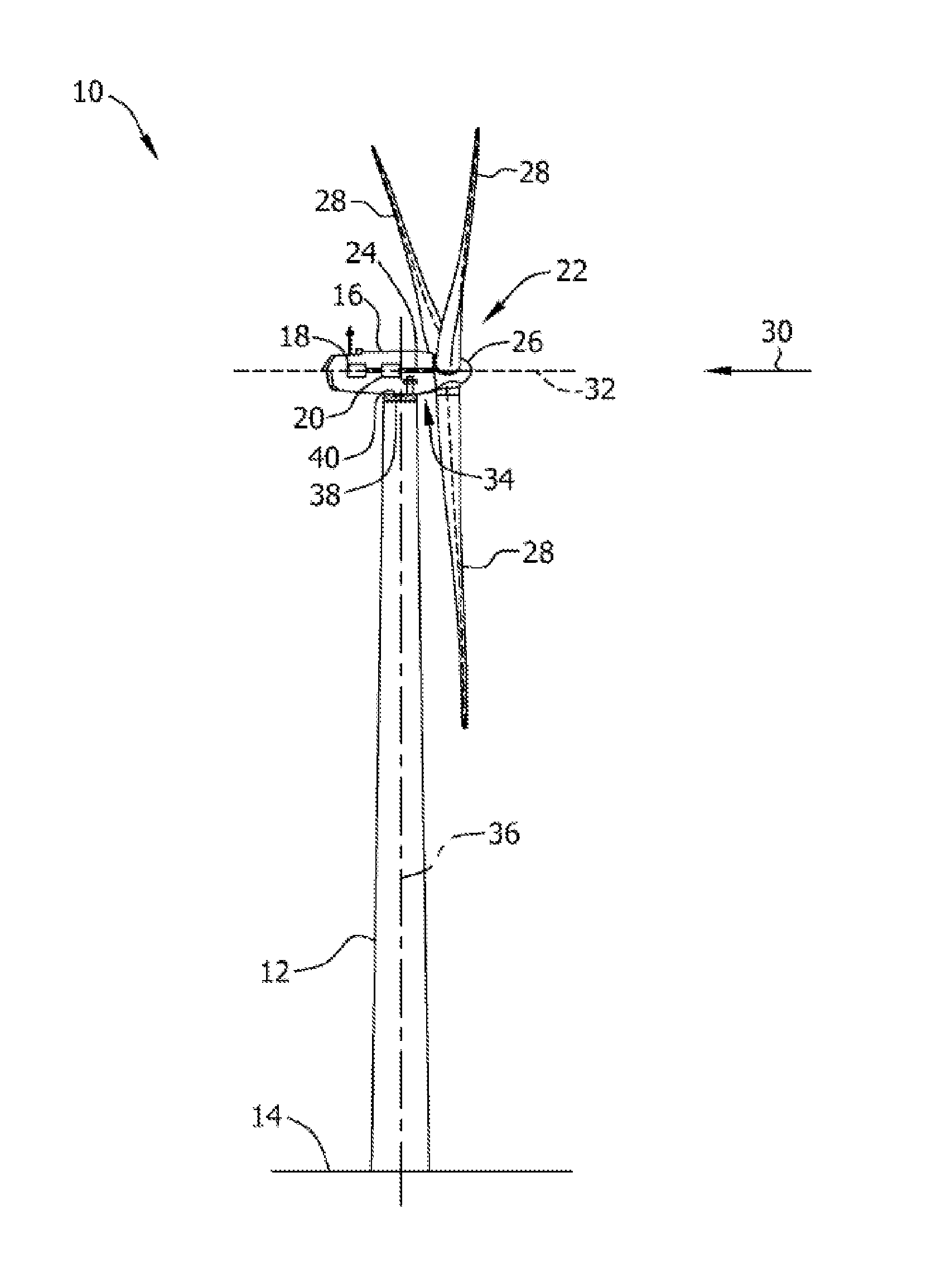
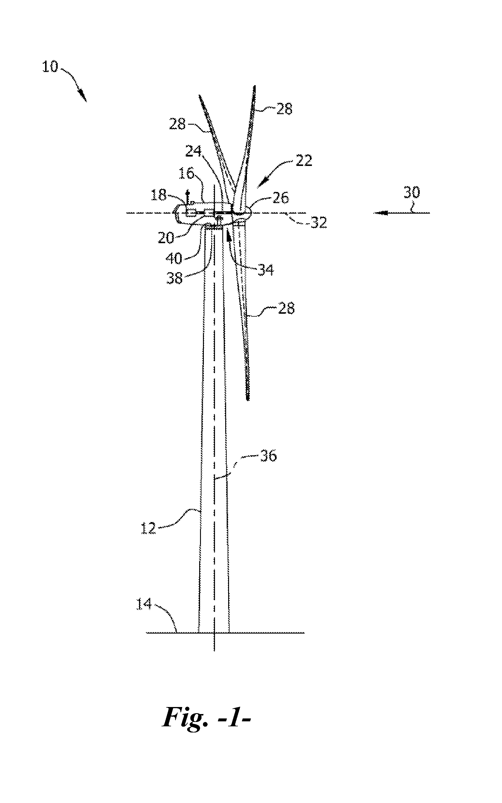
[0023]FIG. 1 is a perspective view of an exemplary wind turbine 10. In the exemplary embodiment, wind turbine 10 is a horizontal-axis wind turbine. Alternatively, wind turbine 10 may be a vertical-axis wind turbine. The wind turbine 10 includes a tower 12 t...


PUM


Abstract

A yaw drive assembly for a wind turbine has a releasable and re-engageable coupling operably configured between a drive gear that engages with a yaw bearing and the output of a gear assembly that is coupled to a drive motor. The coupling maintains a rotational drive engagement between the gear assembly output and drive gear up to a defined rotational torque, wherein the coupling disengages the gear assembly output from the drive gear. The coupling re-engages the gear assembly output to the drive gear upon the rotational torque decreasing to below the defined rotational torque.

Description

FIELD OF THE INVENTION[0001]The present disclosure relates in general to wind turbines, and more particularly to an assembly for limiting yaw drive loads during a yaw slippage event.BACKGROUND OF THE INVENTION[0002]Wind power is considered one of the cleanest, most environmentally friendly energy sources presently available, and wind turbines have gained increased attention in this regard. A modern wind turbine typically includes a tower, generator, gearbox, nacelle, and one or more rotor blades. The rotor blades capture kinetic energy of wind using known foil principles. The rotor blades transmit the kinetic energy in the form of rotational energy so as to turn a shaft coupling the rotor blades to a gearbox, or if a gearbox is not used, directly to the generator. The generator then converts the mechanical energy to electrical energy that may be deployed to a utility grid.[0003]During operation of conventional wind turbines, a yawing device or system may be used to orient the wind t...

Claims


Application Information

Patent Timeline
Patent Type & Authority Applications(United States)
IPC IPC(8): F16H35/10
CPCF03D7/0204F05B2260/4031Y10T74/19614Y02E10/72
Inventor CLOSE, RYANCONRAD, CHAD ROBERTCRUDEN, KRISTINA ANNE
Owner GENERAL ELECTRIC CO
Why Eureka
Try Eureka