Eureka AIR delivers breakthrough ideas for toughest innovation challenges, trusted by R&D personnel around the world.

Xy separate crank mechanism and driving device provided therewith

Active Publication Date: 2014-02-13
TAC RES +1
View PDF10 Cites 15 Cited by
  • Summary
  • Abstract
  • Description
  • Claims
  • Application Information

AI Technical Summary

Benefits of technology

The present invention relates to an XY separate crank mechanism that transmits reciprocating motion by converting the reciprocating motion into rotational motion or transmits rotational motion by converting the rotational motion into reciprocating motion. The invention aims to address frictional loss and sticking phenomena in crank mechanisms by providing a driving apparatus with a cross head or a short piston. The invention also includes various views of the XY separate crank mechanism, such as side views, perspective views, and diagram schematically showing the direction and magnitude of force acting on the mechanism. The technical effects of the invention include reducing frictional loss and sticking phenomena in crank mechanisms, improving smooth reciprocating motion, and reducing high-speed operation limitations.

Problems solved by technology

However, when a large piston is used, oil may run out, which manifests itself as a sticking phenomenon.
However, while it is possible to increase the degree of sealing of the piston by providing a cross head, a frictional loss changing every 180° is caused by a wedge effect at two locations also in the cross head.
Thus, while a reciprocating motion is produced as a motion, a loss is caused by vibration derived from the reciprocating motion.
Thus, a frictional loss is large.
If, for example, a linear slider is arranged on a pair of parallel guides, one linear slider has two bearing trains and a frictional loss is caused by an umbrella opening effect, making a high-speed operation impossible.

Method used


Image

  • Xy separate crank mechanism and driving device provided therewith
  • Xy separate crank mechanism and driving device provided therewith
  • Xy separate crank mechanism and driving device provided therewith

Examples


Embodiment Construction

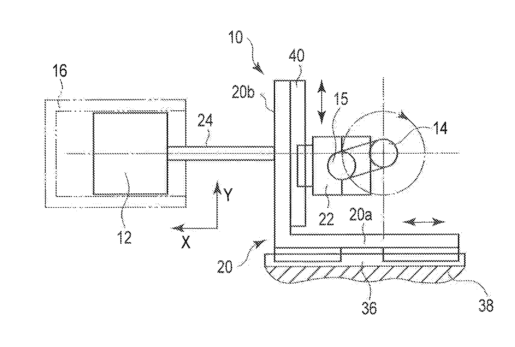
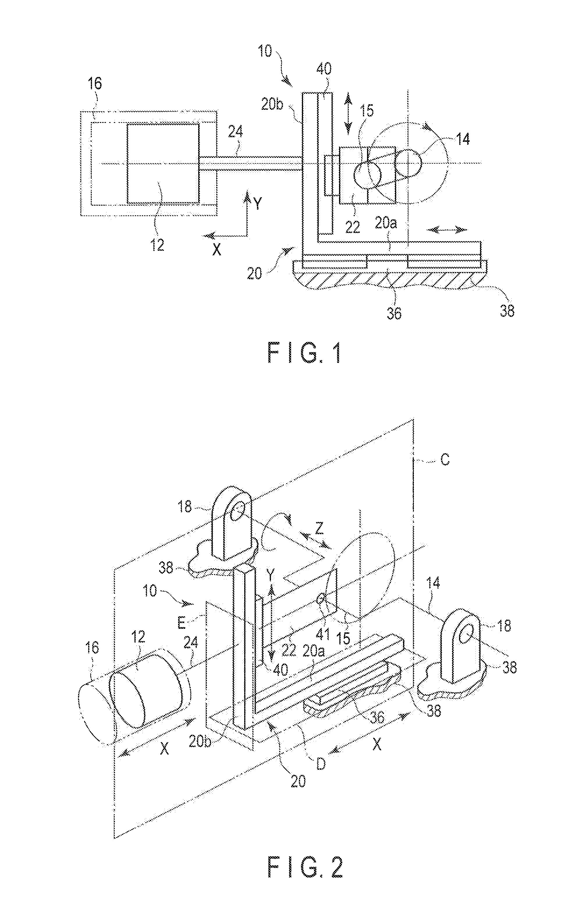
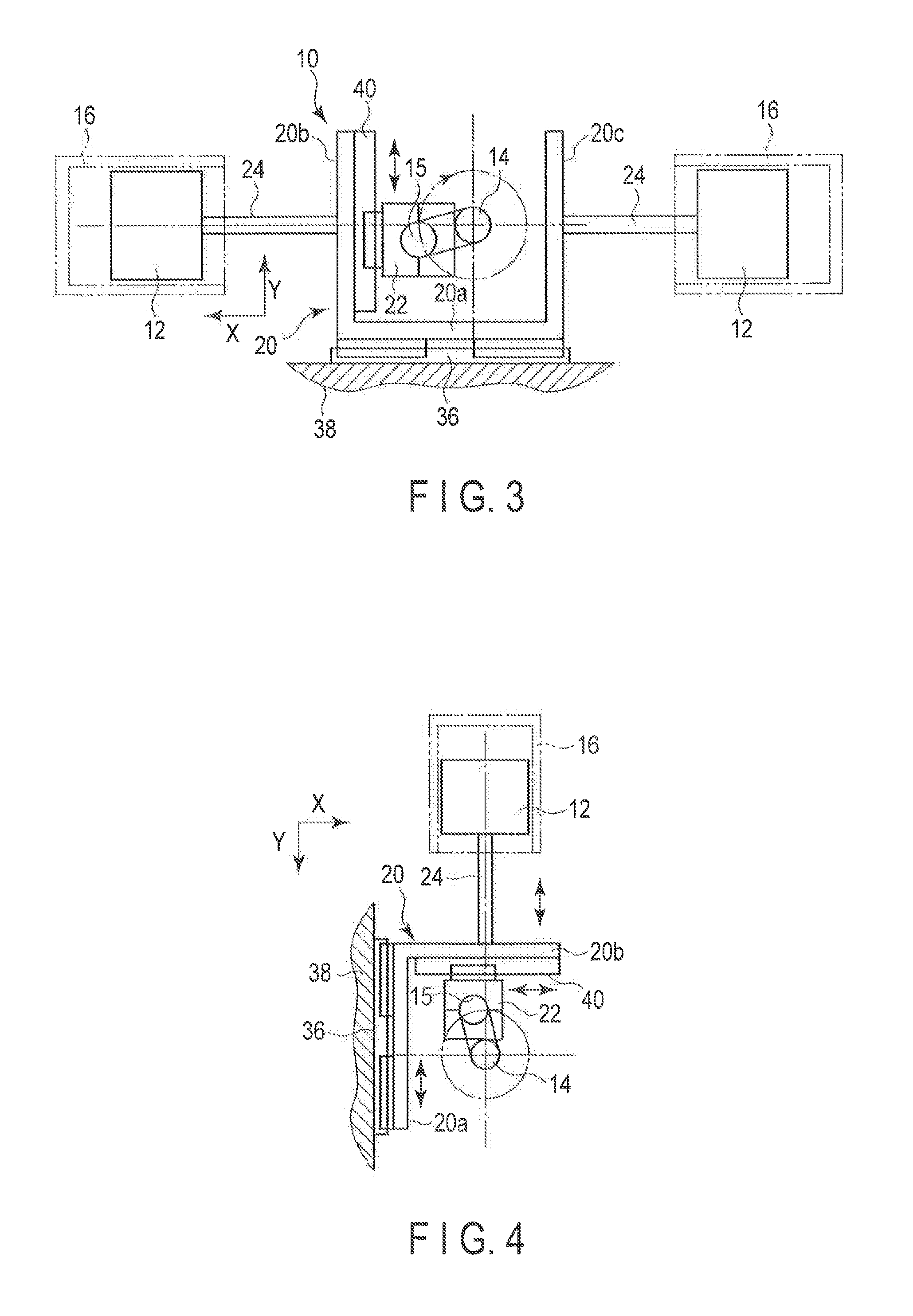
[0061]Z-mechanism XY separate crank mechanisms according to embodiments and various driving apparatus provided therewith will be described below with reference to the drawings. In general, according to an embodiment, an XY separate crank mechanism provided between a movable body reciprocating in a first direction and a rotatable crankshaft to mutually convert reciprocating motion of the movable body and rotational motion of the crankshaft, comprises: a support member provided freely reciprocatingly in the first direction; a crank connecting member mounted on the support member freely reciprocatingly in a second direction perpendicular to the first direction and with which a crank of the crankshaft is rotatably engaged; and a connecting member that connects the piston and the support member and reciprocates in the first direction together with the piston and the support member.

[0062]First, the basic configuration of a Z-mechanism XY separate crank mechanism will be described.

[0063]FI...


PUM


Abstract

An XY separate crank mechanism provided between a movable body reciprocating in a first direction and a rotatable crankshaft to mutually convert reciprocating motion of the movable body and rotational motion of the crankshaft, includes a support member provided freely reciprocatingly in the first direction, a crank connecting member mounted on the support member freely reciprocatingly in a second direction perpendicular to the first direction and with which a crank of the crankshaft is rotatably engaged, and a connecting member configured to connect the piston and the support member and reciprocate in the first direction together with the piston and the support member.

Description

CROSS REFERENCE TO RELATED APPLICATIONS[0001]This application is a Continuation application of PCT Application No. PCT / JP2012 / 056970, filed Mar. 19, 2012 and based upon and claiming the benefit of priority from prior International Patent Application No. PCT / JP2011 / 059956, filed Apr. 22, 2011, the entire contents of all of which are incorporated herein by reference.BACKGROUND OF THE INVENTION[0002]1. Field of the Invention[0003]An embodiment of the present invention relates to an XY separate crank mechanism that transmits reciprocating motion by converting the reciprocating motion into rotational motion or transmits rotational motion by converting the rotational motion into reciprocating motion and a driving apparatus provided therewith.[0004]2. Description of the Related Art[0005]A crank mechanism is known as a mechanism that transmits reciprocating motion by converting the reciprocating motion into rotational motion. For example, engines, compressors and the like include a piston p...

Claims


Application Information

Patent Timeline
IPC IPC(8): F16C3/06
CPCF16C3/06F04B9/04F04B9/042F04B53/006F16H21/36F02B75/32F04B9/02F16H21/18
Inventor YOSHIZAWA, YASUOYOSHIZAWA, TAKUMIYOSHIZAWA, YUTAKAYOSHIZAWA, SATOSHI
Owner TAC RES
Why Eureka
Eureka Blog
Learn More