Touch panel

a touch panel and touch technology, applied in the field of touch panels, can solve the problems of insufficient uniformity, linear wiring and uneven pattern of electrodes, current use of keyboards and mouse as input devices to effectively drive products, etc., and achieve the effect of improving visibility

Inactive Publication Date: 2014-02-13
SAMSUNG ELECTRO MECHANICS CO LTD
View PDF3 Cites 33 Cited by
  • Summary
  • Abstract
  • Description
  • Claims
  • Application Information

AI Technical Summary

Benefits of technology

[0019]The present invention has been made in an effort to provide a touch panel in which an electrode and a wiring of a transparent substrate are formed to have a uniform pattern, thus having enhanced visibility.

Problems solved by technology

However, the rapid increase of an information-oriented society has extended the purpose of computers, such that a currently used key board and mouse serving as input devices are insufficient to effectively drive products.
The reason why the wirings are disposed in the non-active region is because the wirings generally have a linear shape, so it does not have uniformity in a pattern with the electrodes disposed in the active region of the transparent substrate.
In other words, when the electrodes are formed to have a mesh pattern, the linear wirings and the electrodes are not uniform in pattern.
Thus, if electrodes and wirings are formed together in an active region, visibility of the touch panel deteriorates.
Such shortcomings are an obstacle to reducing the size of terminals employing a touch panel structure or incur the necessity of reducing an active region of a transparent substrate as a touch region of a device having the same size.

Method used


Image

  • Touch panel
  • Touch panel
  • Touch panel

Examples


first embodiment

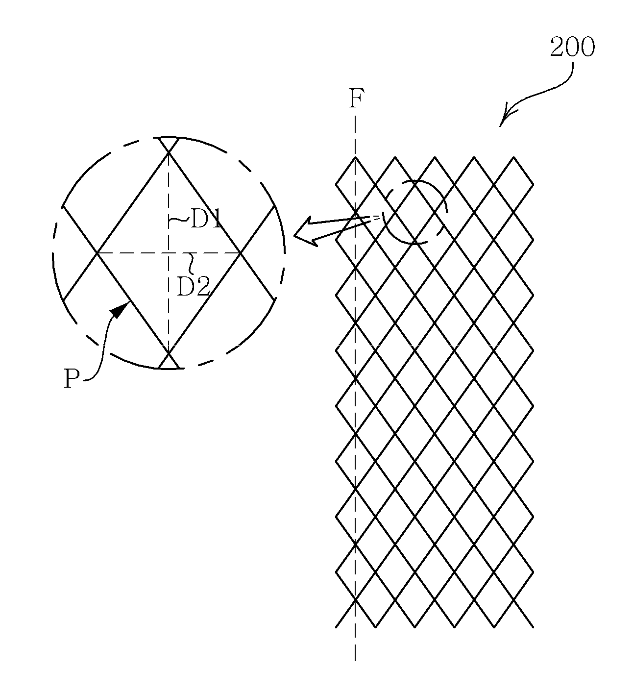
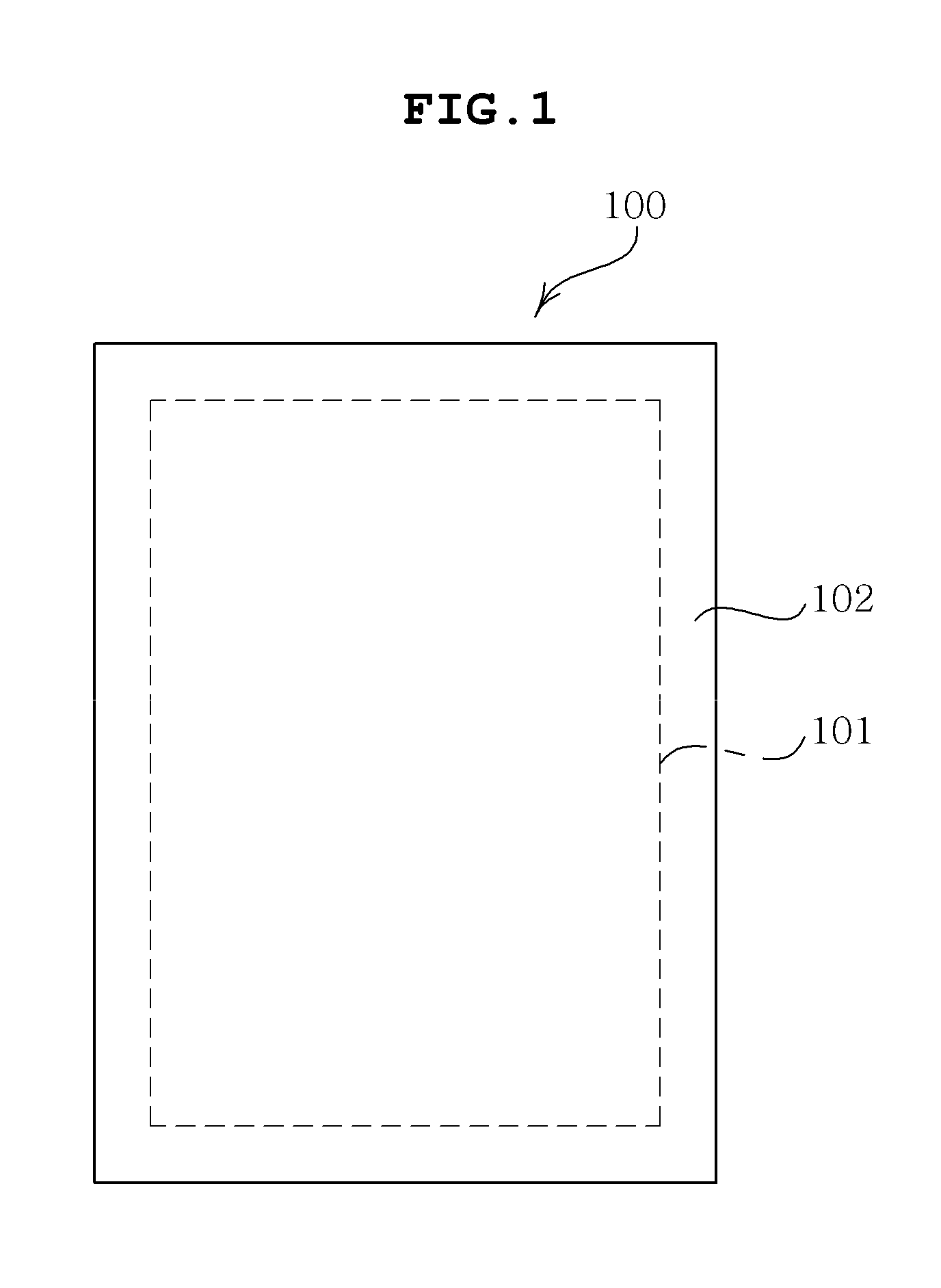
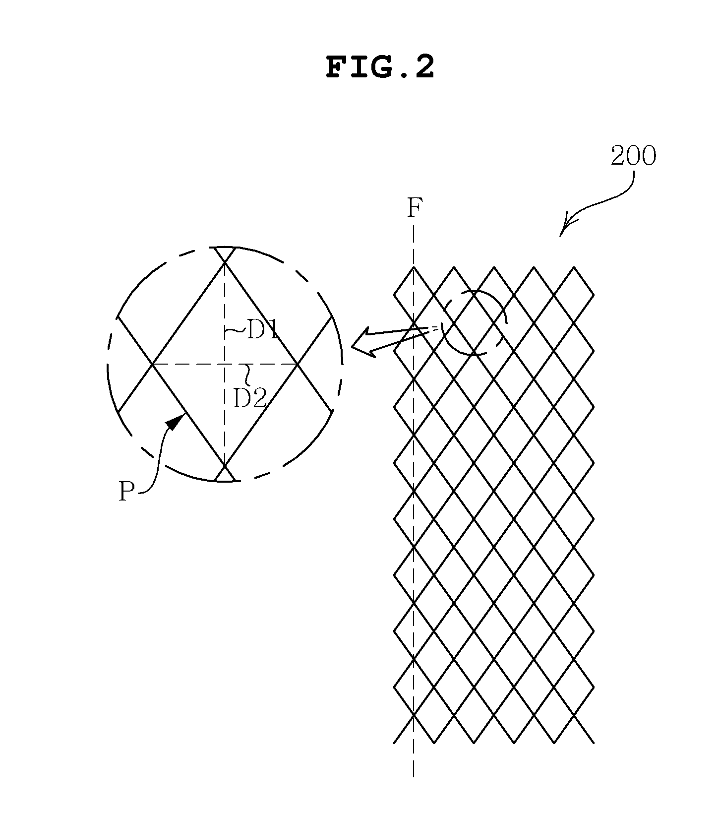
[0054]Referring to FIGS. 1 through 4, a touch panel according to the present invention includes a transparent substrate 100, an electrode (or electrodes) 200 formed to have a mesh pattern on the transparent substrate 100, and a wiring (or wirings) 300 formed to have a zigzag pattern and having first and second peaks alternately continued in a length direction on the transparent substrate 100, and connected to the electrode 200.

[0055]The transparent substrate 100 serves to provide a region in which the electrode 200 and the wiring 300 are to be formed. The transparent substrate 100 is required to have bearing power sufficient to support the electrode 200 and the wiring 300 and transparency allowing a user to recognize an image provided by the image display device.

[0056]When the foregoing bearing power and transparency are considered, preferably, the transparent substrate 100 is made of polyethylene terephthalate (PET), polycarbonate (PC), polymethyl methacrylate (PMMA), polyethylene ...

second embodiment

[0077]FIG. 5 is a plan view of a major part illustrating an electrode array and a wiring array of touch panel according to the present invention. FIG. 6 is an enlarged view of the major part illustrating the wiring array depicted in FIG. 5. FIGS. 7 to 10 are enlarged views of major parts illustrating various examples of the wiring array depicted in FIG. 5.

[0078]Referring to FIGS. 5 through 8, a touch panel according to the present embodiment includes the transparent substrate 100 (See FIG. 1), an electrode array 400 formed to have a mesh pattern on the transparent substrate 100 and divided into a first electrode 410 and a second electrode 420 by a cutout portion 401 formed on the mesh pattern, and a wiring array 500 including a first wiring 510 and a second wiring 520 formed to have a zigzag pattern on the transparent substrate 100 and having first peaks 511 and 521 and second peaks 512 and 522 alternately continued in a length direction, and here, the first wiring 510 is connected ...


PUM


Abstract

Disclosed herein is a touch panel including a transparent substrate, an electrode formed to have a mesh pattern on the transparent substrate, and a wiring formed to have a zigzag pattern on the transparent substrate, having first and second peaks alternately continued in a length direction, and connected to the electrode. Since the electrode and the wiring are formed to have a uniform pattern overall, the electrode and the wiring can be disposed in an active region of the touch panel, and thus, a bezel region can be reduced.

Description

CROSS REFERENCE TO RELATED APPLICATION[0001]This application claims the benefit of Korean Patent Application No. 10-2012-0088506, filed on Aug. 13, 2012, entitled “Touch Panel”, and Korean Patent Application No. 10-2012-0108048, filed Sep. 27, 2012, entitled “Touch Panel”, both of which are incorporated by reference herein in their entireties.BACKGROUND OF THE INVENTION[0002]1. Technical Field[0003]The present invention relates to a touch panel.[0004]2. Description of the Related Art[0005]Due to the development of computers using digital technologies, computer assisted devices have also been developed, and personal computers, portable transmission devices, and other personal dedicated information processing devices perform text and graphic processing by using various input devices such as a key board or a mouse.[0006]However, the rapid increase of an information-oriented society has extended the purpose of computers, such that a currently used key board and mouse serving as input de...

Claims


Application Information

Patent Timeline
Patent Type & Authority Applications(United States)
IPC IPC(8): H01H1/06
CPCH01H1/06G06F3/04164G06F2203/04112G06F3/044G06F2203/04111
Inventor YIM, JUNG RYOULHONG, SANG SUJANG, IN HYUNKIM, SEUL GILEE, KYU SANGYANG, CHUNG MO
Owner SAMSUNG ELECTRO MECHANICS CO LTD
Why Eureka
Try Eureka