
Electronic apparatus and power management method

a technology of electronic equipment and management method, applied in the integration of power network operation system, emergency power supply arrangement, instruments, etc., can solve the problems of high energy consumption in standby mode, affecting the efficiency of power supply, waste of unnecessary power, etc., and achieve the goal of energy saving

Inactive Publication Date: 2014-02-13
DARWIN PRECISIONS CORP
View PDF5 Cites 10 Cited by
  • Summary
  • Abstract
  • Description
  • Claims
  • Application Information

AI Technical Summary

Benefits of technology

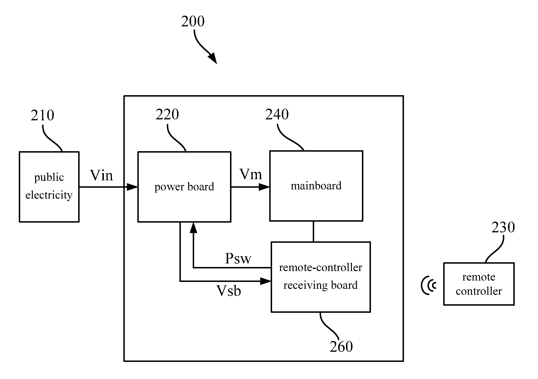
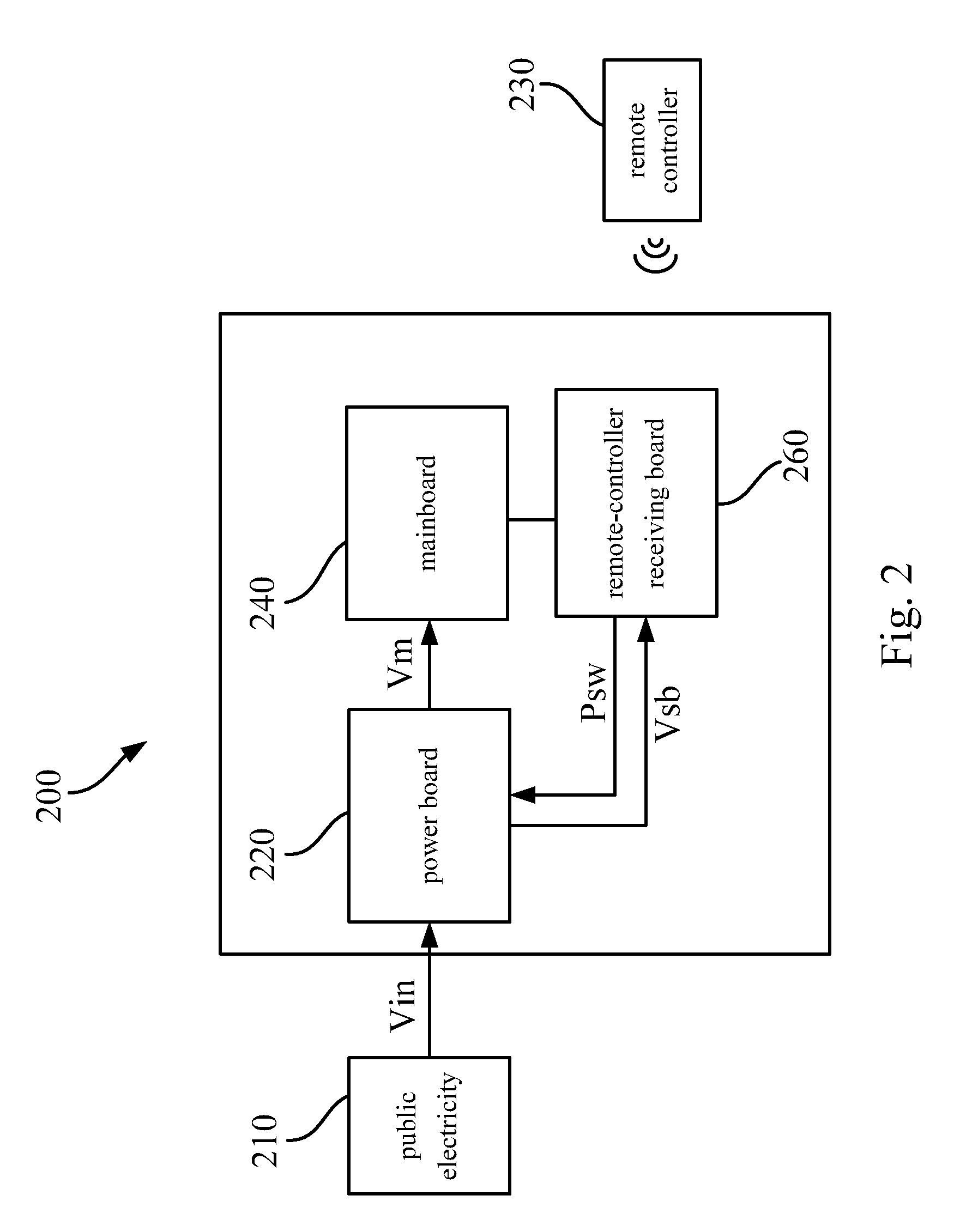
The patent describes a method for managing power in an electronic device with a power board, a remote-controller receiving board, and a mainboard. The method involves converting public electricity into a standby voltage and supplying the remote-controller receiving board with it. A power-switching signal is then generated to the power board when the remote-controller receiving board receives a control signal. The mainboard can then be selectively powered with the main power voltage or have the supply of power ended based on the power-switching signal. This system allows for efficient management of power in electronic devices.

Problems solved by technology

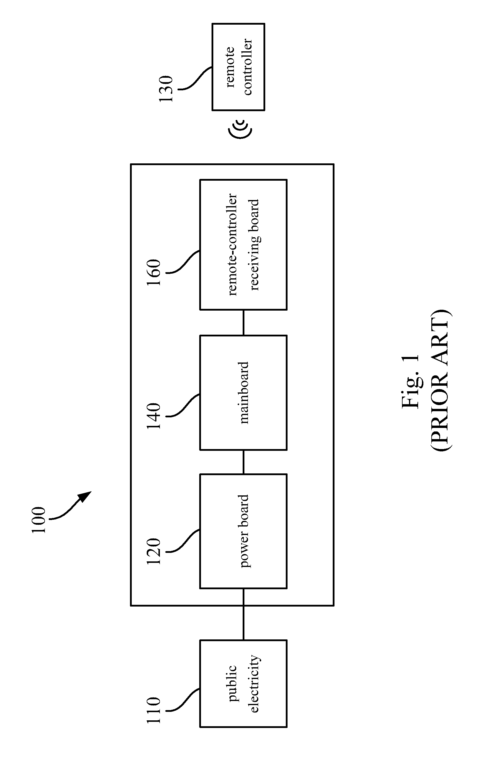
In other words, conventional appliances still cause a certain degree of standby power consumption even when the appliances are turned off.
As a result, the electronic apparatus 100 will waste unnecessary power and have high energy consumption in the standby mode, and it is against the goal of energy-saving.

Method used


Image

  • Electronic apparatus and power management method
  • Electronic apparatus and power management method
  • Electronic apparatus and power management method

Examples


Embodiment Construction

[0017]In the following description, several specific details are presented to provide a thorough understanding of the embodiments of the present disclosure. One skilled in the relevant art will recognize, however, that the present disclosure can be practiced without one or more of the specific details, or in combination with or with other components, etc. In other instances, well-known implementations or operations are not shown or described in detail to avoid obscuring aspects of various embodiments of the present disclosure.

[0018]Reference is made to FIG. 2, which is a schematic diagram illustrating an to electronic apparatus 200 according to an embodiment of the disclosure. The electronic apparatus 200 includes a power board 220, a mainboard240 and a remote-controller receiving board 260. The power board 220 is configured for converting a public electricity input signal Vin of public electricity 210 into a standby voltage Vsb and a main power voltage Vm. The remote-controller rec...


PUM


Abstract

The disclosure discloses an electronic apparatus and a power management method are disclosed. The electronic apparatus includes a power board, a remote-controller receiving board and a mainboard. The power board is configured for converting public electricity into a standby voltage and a main power voltage. The remote-controller receiving board, coupled with the power board, is configured to be operated with the standby voltage. When the remote-controller receiving board receives a control signal from a remote controller, the remote-controller receiving board sends a power-switching signal to the power board. The power board starts or stops supplying the main power voltage according to the power-switching signal. The mainboard, coupled with the power board, is configured to be operated with the main power voltage.

Description

RELATED APPLICATIONS[0001]This application claims priority to Taiwan Application Serial Number 101128793, filed Aug. 9, 2012, which is herein incorporated by reference.BACKGROUND[0002]1. Technical Field[0003]The present disclosure relates to an electronic devices and a power to management method thereof. More particularly, the present disclosure relates to an electronic device capable of reducing its standby power consumption and a power management method thereof.[0004]2. Description of Related Art[0005]Environmental issues are highly concerned in the modern society. Appliances or electronic equipments are requested to reduce energy consumption. The energy-saving appliances are regarded as the mainstream of appliances. In general applications, the appliances are connected to the public electricity outlet for long. Even not being activated, the appliances stay in a standby mode. For example, when the television is turned off, the television is not disconnected from the power source b...

Claims


Application Information

Patent Timeline
IPC IPC(8): H02J9/00
CPCH02J9/005G06F1/26G06F1/3203Y02B70/30Y04S20/20
Inventor YU, CHENG-HUNG
Owner DARWIN PRECISIONS CORP
Learn More