
Liquid ejecting apparatus

a technology of liquid ejecting apparatus and ejector, which is applied in the direction of printing, other printing apparatus, etc., can solve the problems of reducing the sealing effect, requiring a large amount of force for installing the ink tank, and generating considerable counterforce, etc., to achieve the effect of facilitating the elastic member to be set in pla

Active Publication Date: 2014-02-13
SEIKO EPSON CORP
View PDF2 Cites 2 Cited by
  • Summary
  • Abstract
  • Description
  • Claims
  • Application Information

AI Technical Summary

Benefits of technology

The patent describes a mounting mechanism that allows objects to be attached to a device using a pivot. This connection allows for a reduced force between the upstream and downstream flow paths. The mechanism includes an abutment portion that is sealed to the device using an elastic member. The elastic member is designed to secure the abutment portion around the liquid introduction path, even when the object is pivoted during mounting. This ensures a sufficient sealing effect at the joint portion in the liquid flow path while minimizing the force required for the attachment. The elastic member is designed to flexurally deform in a specific direction when pressed against the abutment portion, preventing any counterforces and ensuring the seal is secure. The design also allows for flexural deformation in a specific direction while securing space for the elastic member to depressurize, further preventing the elastic member from coming off during mounting or removal. The elastic member is symmetrically shaped in both directions, allowing for easy placement in the mounting mechanism. Overall, the invention provides a simple and secure mounting mechanism for objects to the device.

Problems solved by technology

However, the O-ring generates considerably large counterforce upon being elastically deformed, and hence requires large force for installing the ink tank.
However, in the case where the ink tank is brought into contact with the elastic member via the peripheral projection as above, a decrease in contact area therebetween leads to a degraded sealing effect.
In particular, when the ink tank is made to pivot in the mounting process the peripheral projection may collapse in the pivoting direction.
In such a case, the elastic member may fail to provide a sufficient sealing effect, compared with the case where the ink tank is mounted in a linear motion from the side of the outlet toward the supply tube.
Further, the mentioned drawback is incidental not only to such printers that include the holder on which the ink tank can be mounted, but broadly to liquid ejecting apparatuses having an elastic member for sealing a joint portion in a liquid flow path.

Method used


Image

  • Liquid ejecting apparatus
  • Liquid ejecting apparatus
  • Liquid ejecting apparatus

Examples


Embodiment Construction

[0035]Hereafter, a liquid ejecting apparatus according to an embodiment of the invention will be described referring to the drawings.

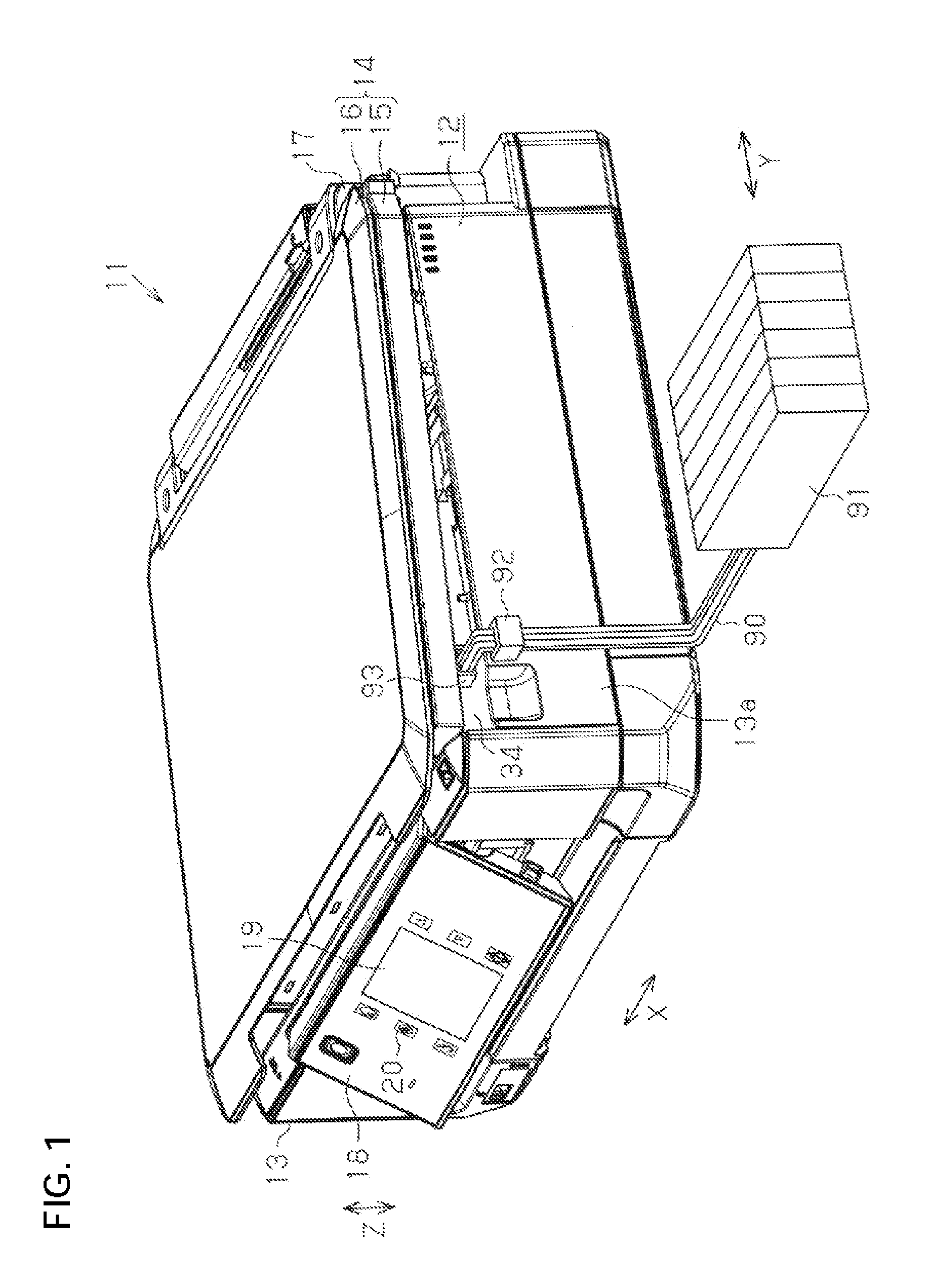
[0036]As shown in FIG. 1, a multifunction printer 11 includes a liquid ejecting apparatus 12, and a scanner unit 14 superposed thereon in the anti-gravity direction and coupled to a main casing 13 of the liquid ejecting apparatus 12. In the following description, the anti-gravity direction will be referred to as upward direction, the gravity direction will be referred to as a downward direction, and a third direction along the upward and downward direction will be indicated as up-down direction Z in the drawings.

[0037]The scanner unit 14 includes a scanner main body 15 coupled to the liquid ejecting apparatus 12, and a cover 16 provided on the upper side of the scanner main body 15. The scanner unit 14 can be opened and closed with respect to the main casing 13 via a pivotal mechanism 17 such as a hinge provided at an end portion of the scanner unit 14...


PUM


Abstract

A liquid ejecting apparatus includes a liquid ejecting head, a mounting mechanism including a downstream flow path, a cartridge including an upstream flow path to be communicably connected to the downstream flow path when the cartridge is attached to the mounting mechanism and an annular projection, and configured to be mounted on the mounting mechanism by being made to pivot, a carriage that reciprocates in a predetermined stroke region carrying thereon the liquid ejecting head and the mounting mechanism, a liquid supply tube connecting between a liquid tank located outside the stroke region and the upstream flow path, and an elastic member of an annular shape having a larger outer diameter than that of the annular projection and a smaller inner diameter than that of the annular projection and disposed to surround a liquid introduction path, the elastic member including an abutment portion.

Description

BACKGROUND[0001]1. Technical Field[0002]The present invention relates to a liquid ejecting apparatus that ejects a liquid supplied from a liquid chamber.[0003]2. Related Art[0004]Liquid ejecting apparatuses thus far developed include an ink jet printer (hereinafter, simply “printer”) that ejects ink, an example of the liquid, onto a recording medium such as a paper sheet thereby performing a recording operation. Such printers generally include a holder on which an ink tank serving as a supply source of the ink is mounted. Some of the holders include a supply tube connected to an outlet of the ink tank, and an annular elastic member disposed to surround the supply tube so as to seal the joint portion between the outlet and the supply tube.[0005]An example of the elastic member for sealing the joint portion in the liquid flow path is an O-ring having a circular cross-sectional shape. However, the O-ring generates considerably large counterforce upon being elastically deformed, and hen...

Claims


Application Information

Patent Timeline
Patent Type & Authority Applications(United States)
IPC IPC(8): B41J2/175
CPCB41J2/175B41J2/17513B41J2/1752B41J2/17553B41J29/02B41J29/13
Inventor HARA, KEIJI
Owner SEIKO EPSON CORP
Learn More