Display apparatus, information processing system and recording medium

a technology of information processing system and display device, applied in the field of display device, can solve problems such as user inability to provide, and achieve the effect of reducing the moving rate of the pointer

Inactive Publication Date: 2014-02-13
SHARP KK
View PDF27 Cites 24 Cited by
  • Summary
  • Abstract
  • Description
  • Claims
  • Application Information

AI Technical Summary

Benefits of technology

[0021]According to the present invention, the reception unit wirelessly receives coordinate values associated with continuous contact input in an input apparatus having a touch pad or a touch panel. The display processing unit makes the display unit display the pointer moving on the basis of the coordinate values received by the reception unit. The reducing unit reduces the moving rate of the pointer on the basis of the coordinate values received by the reception unit, when the distance between an object displayed on the display unit and the pointer displayed on the display unit is within a predetermined distance. The output unit outputs acceptance information indicating that an input is accepted at the final coordinate values for the pointer displayed by the display unit, when the continuous contact input is finished.

Problems solved by technology

The input technique disclosed in the conventional technology, however, has such a problem in that a user may not be provided with an operation environment for a display apparatus which tends to have an increased amount of information to be displayed.

Method used


Image

  • Display apparatus, information processing system and recording medium
  • Display apparatus, information processing system and recording medium
  • Display apparatus, information processing system and recording medium

Examples


embodiment 1

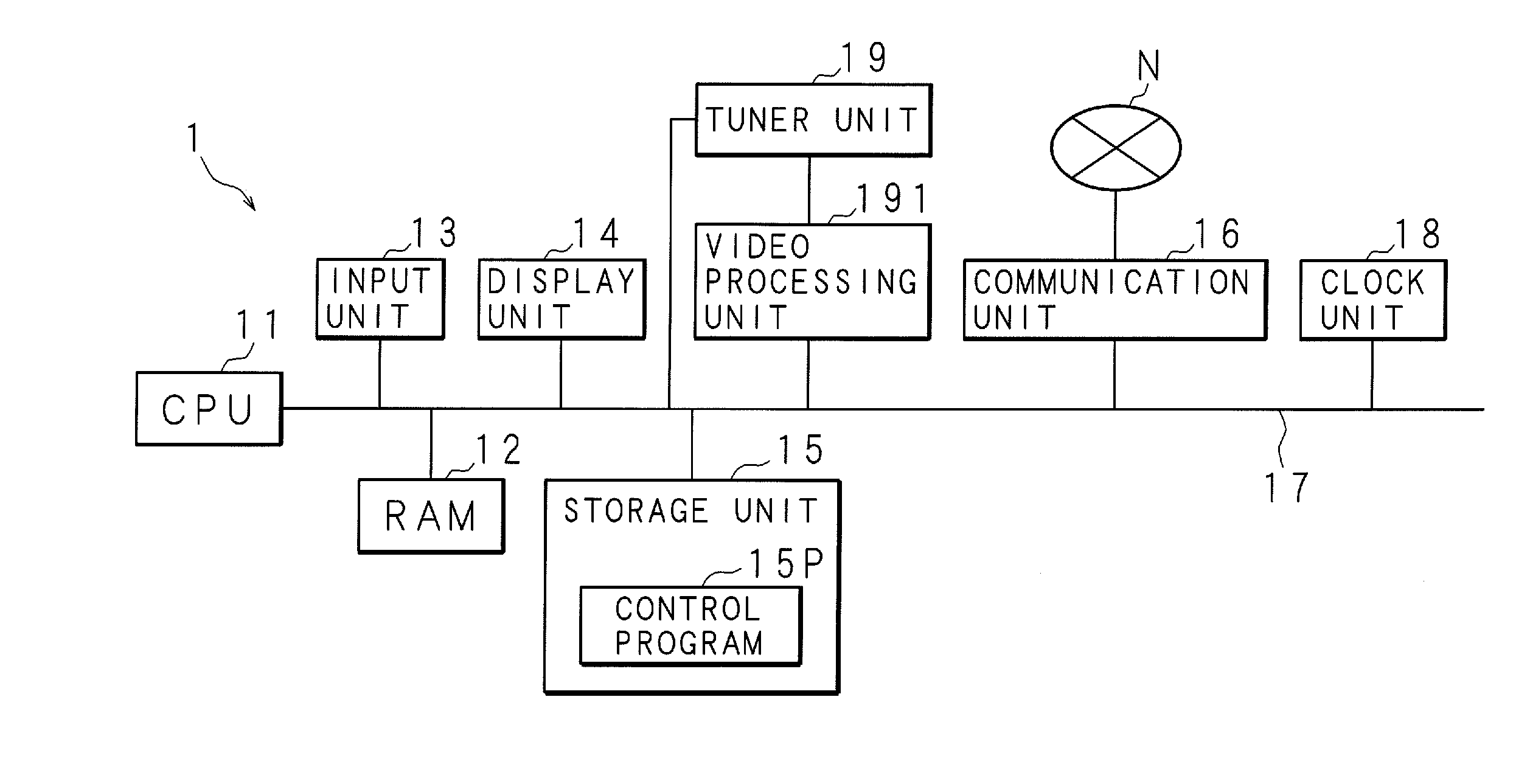
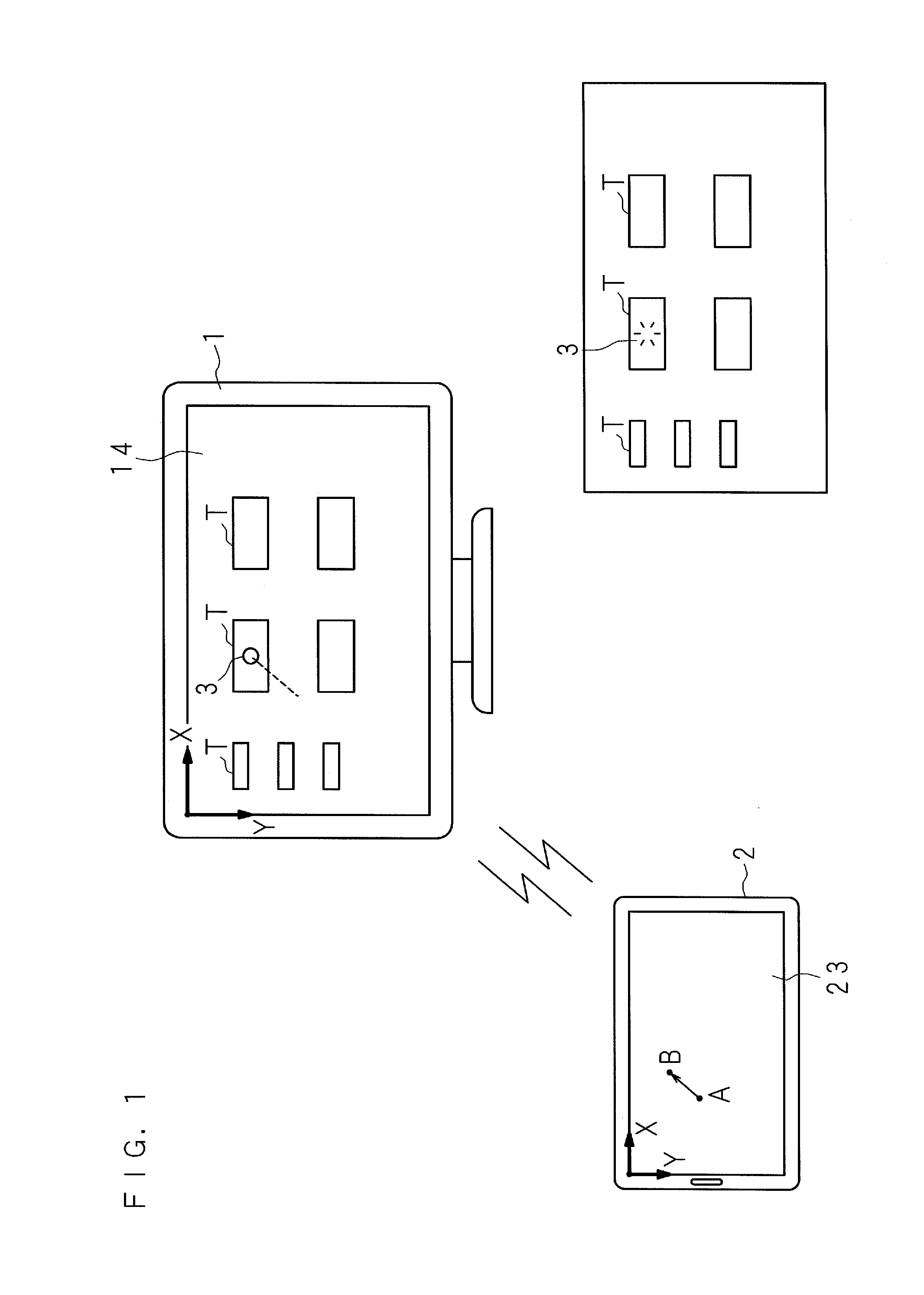
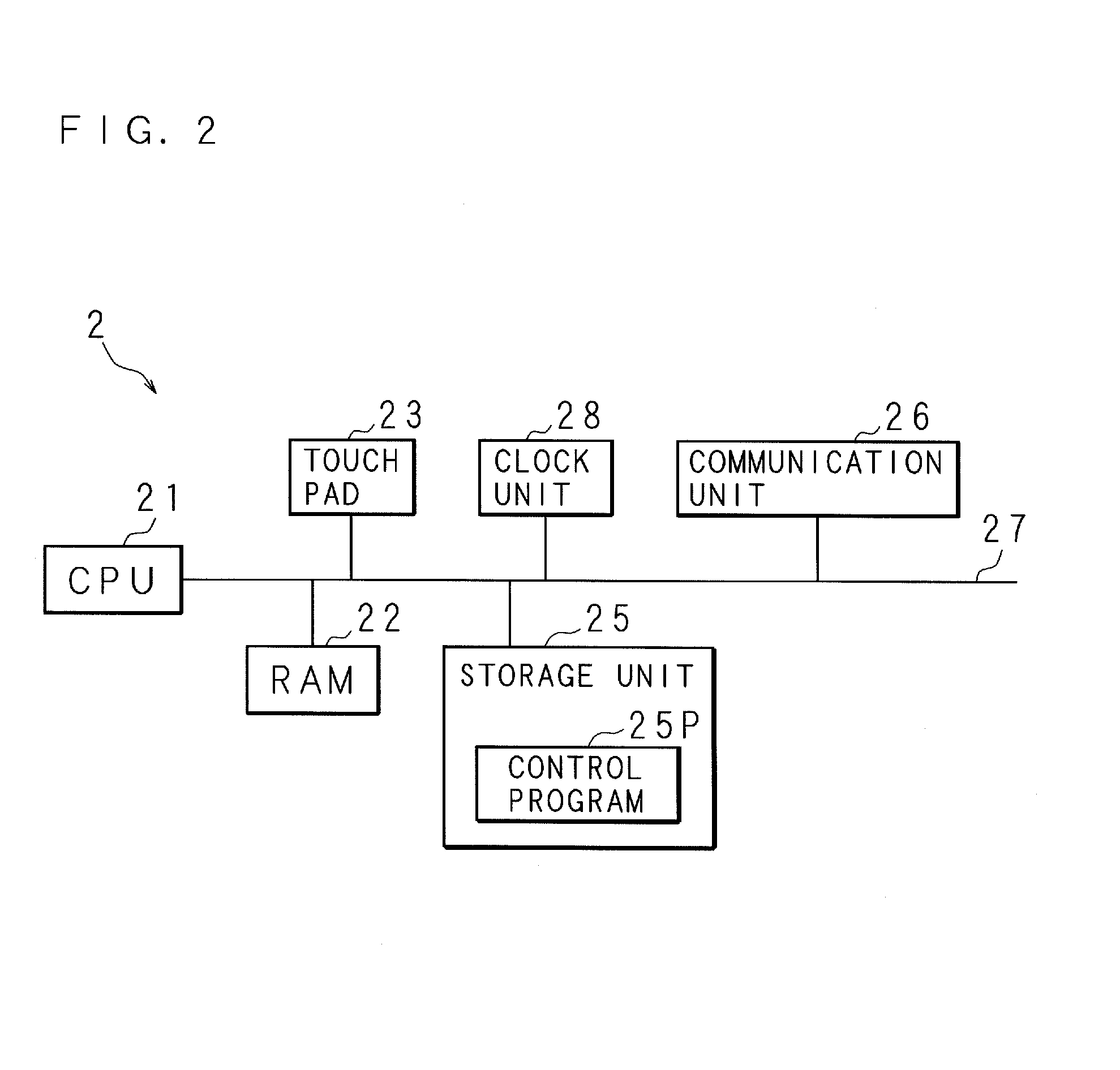
[0073]Embodiments will now be described below with reference to the drawings. FIG. 1 is a schematic view illustrating an outline of an information processing system. The information processing system includes a display apparatus 1, an input apparatus 2 and the like. The display apparatus 1 is, for example, a television, a television with a built-in recording device, a personal computer, or a computer for controlling medical equipment, a semiconductor manufacturing device, a working machine or the like. In the present embodiment, an example is described where a television 1 is used as the display apparatus 1. The input apparatus 2 is an apparatus having a touch pad or a touch panel, and functions as a remotely-operated device (hereinafter referred to as “remote controller”) for the television 1. As the input apparatus 2, for example, in addition to a remote controller with touch pad formed on the surface of its housing, a PDA (Personal Digital Assistant) with a touch panel, a portabl...

embodiment 2

[0090]Embodiment 2 relates to an example where the indication of the pointer 3 is changed. FIGS. 7 and 8 illustrate a flowchart indicating a procedure of change processing. The CPU 21 in the remote controller 2 determines whether or not contact is detected through the touch pad 23 (step S71). If contact is not detected (NO at step S71), the CPU 21 waits until contact is detected. If contact is detected (YES at step S71), the CPU 21 acquires coordinate values at the position of contact (step S72). The CPU 21 determines whether or not non-contact is detected after contact is detected (step S73).

[0091]If it is determined that non-contact is not detected (NO at step S73), the CPU 21 transmits the acquired coordinate values to the television 1 through the communication unit 26 (step S74). The CPU 21 returns to step S72 and repeats processing described above. The CPU 11 of the television 1 receives coordinate values transmitted wirelessly through the communication unit 16 (step S75). The ...

embodiment 3

[0106]Embodiment 3 relates to an example in which tap input is performed after the processing of changing the pointer 3. After changing the pointer 3, tap operation may be performed for input processing. FIGS. 12 and 13 illustrate a flowchart indicating a procedure of display processing according to Embodiment 3. Since the processing from steps S71 through S84 is similar to that described earlier, details thereof will not be described here. If it is determined that coordinate values and non-contact information are not received (NO at step S84), the CPU 11 proceeds to step S121. The CPU 11 acquires coordinate values transmitted from the remote controller 2 (step S121). The CPU 11 determines whether or not the acquired coordinate values are out of a predetermined range (step S122). More specifically, it is determined whether or not the difference between the coordinate values for the pointer 3 changed at step S82 and the coordinate values acquired at step S121 exceeds the threshold st...


PUM


Abstract

A wireless output unit of a remote controller having a touch pad or a touch panel wirelessly outputs a coordinate value associated with a continuous contact input for the touch pad to a television. A reception unit of the television wirelessly receives the coordinate value associated with the continuous contact input. A display processing unit displays on a display unit a pointer moving on the basis of the coordinate value received by the reception unit. A reducing unit reduces the moving rate of the pointer 3 on the basis of the coordinate value received by the reception unit, when the distance between an object T displayed on the display unit and the pointer 3 displayed on the display unit is within a predetermined distance. An output unit outputs, when the continuous contact input is finished, acceptance information indicating that an input for an object T displayed on the display unit is accepted at a final coordinate value for the pointer 3 displayed on the display unit.

Description

CROSS-REFERENCE TO RELATED APPLICATIONS[0001]This application is the national phase under 35 U.S.C. §371 of PCT International Application No. PCT / JP2012 / 058816 which has an International filing date of Apr. 2, 2012 and designated the United States of America.FIELD[0002]The present invention relates to a display apparatus that displays information, an information processing system and a recording medium.BACKGROUND AND SUMMARY[0003]A display apparatus for a television, a personal computer or the like is operated with a remote controller. For example, a coordinate input apparatus described in Japanese Patent Application Laid-Open No. 2008-192012 discloses a technique for adjusting coordinates at the center of a contact region of a touch pad. In addition, a technique related to control processing for a touch pad and a touch panel is known (see Japanese Patent Application Laid-Open No. 2002-82766, Japanese Patent Application Laid-Open No. 2001-117713, Japanese Patent Application Laid-Ope...

Claims


Application Information

Patent Timeline
Patent Type & Authority Applications(United States)
IPC IPC(8): H04N21/422G06F3/0481G06F3/0488
CPCH04N21/42224G06F3/0488G06F3/03547G08C17/02G08C23/04
Inventor MOTOYAMA, TADASHIKUMATA, AKIHIROOISHI, TAKATOSHI
Owner SHARP KK
Why Eureka
Try Eureka