
Method of anchoring a connector, and connector

a technology of connectors and connectors, applied in the direction of sheet joining, furniture joining, lamination, etc., can solve the problems of insufficient mechanical stability between the building layers provided by the interlining, and difficulty in attaching objects to lightweight building elements

Active Publication Date: 2014-02-13
WOODWELDING
View PDF0 Cites 21 Cited by
  • Summary
  • Abstract
  • Description
  • Claims
  • Application Information

AI Technical Summary

Benefits of technology

The invention provides a method to anchor a connector for use in lightweight building elements, which helps stabilize the connection between two buildings. The method ensures that the connector is secure and can withstand the load of the building. The technical effect of the invention is to provide a reliable and durable connection between two building objects.

Problems solved by technology

However, because the building layers are thin and the interlining is not suitable for anchoring a connector—such as a dowel—in it, it is difficult to attach an object to the lightweight building elements other then just by gluing it to the element's surface.
Also, in some cases the mechanical stability between the building layers provided by the interlining is insufficient, and additional means for providing the stability would be desired.

Method used


Image

  • Method of anchoring a connector, and connector
  • Method of anchoring a connector, and connector
  • Method of anchoring a connector, and connector

Examples


Embodiment Construction

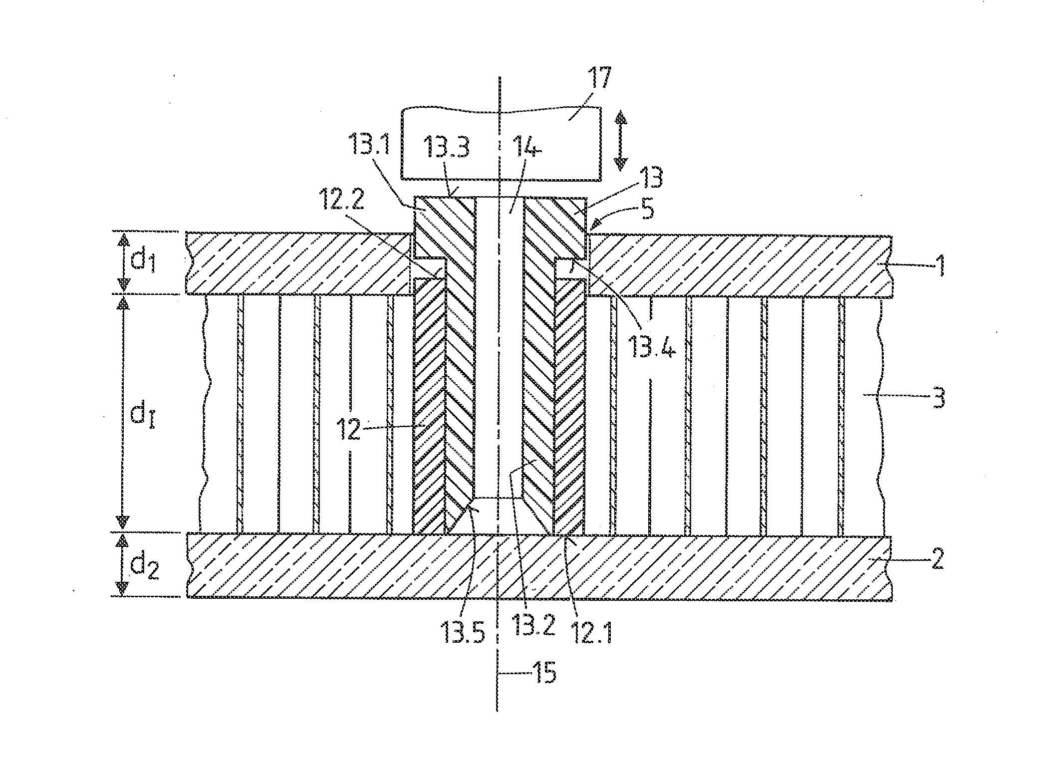
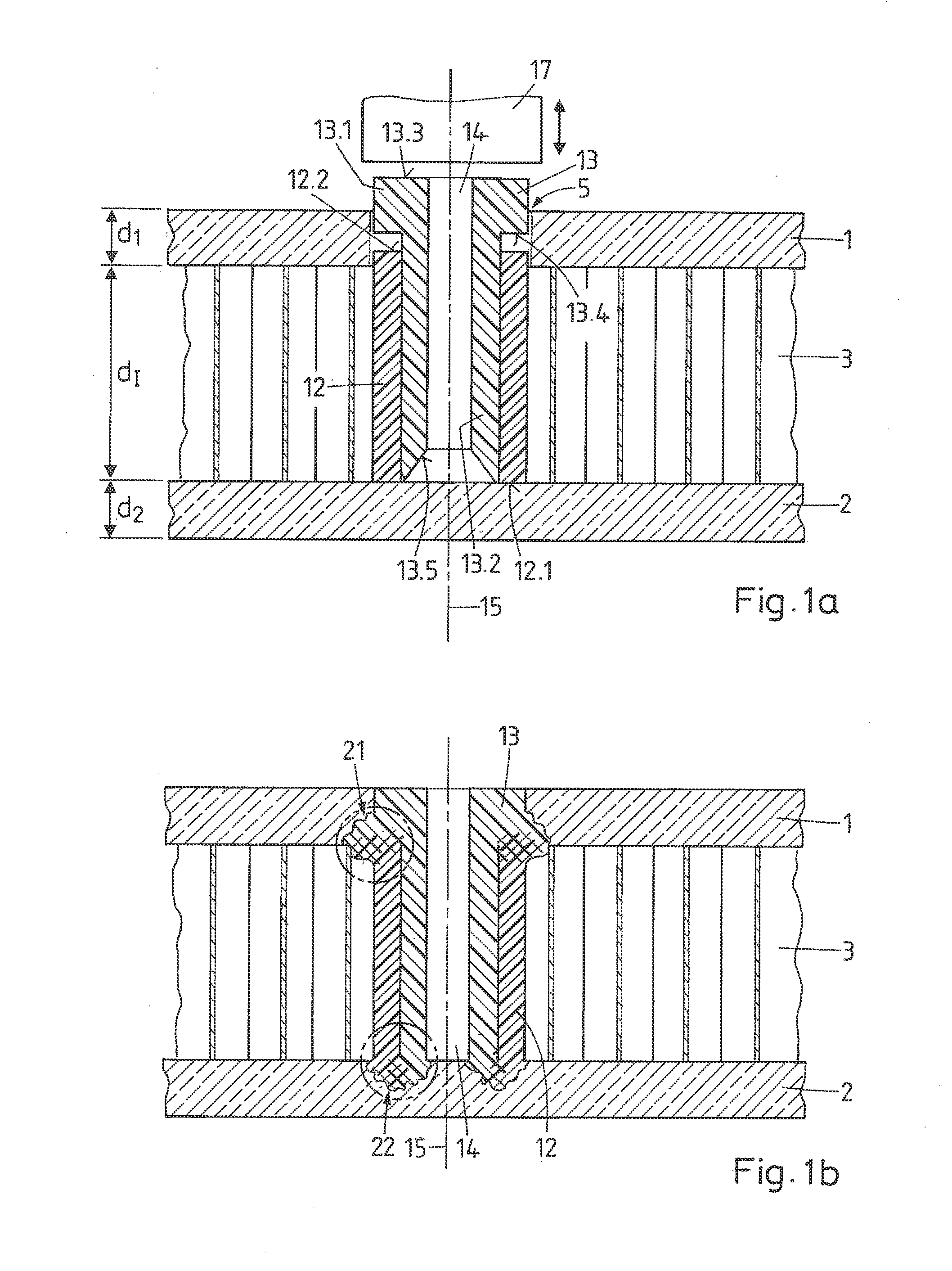
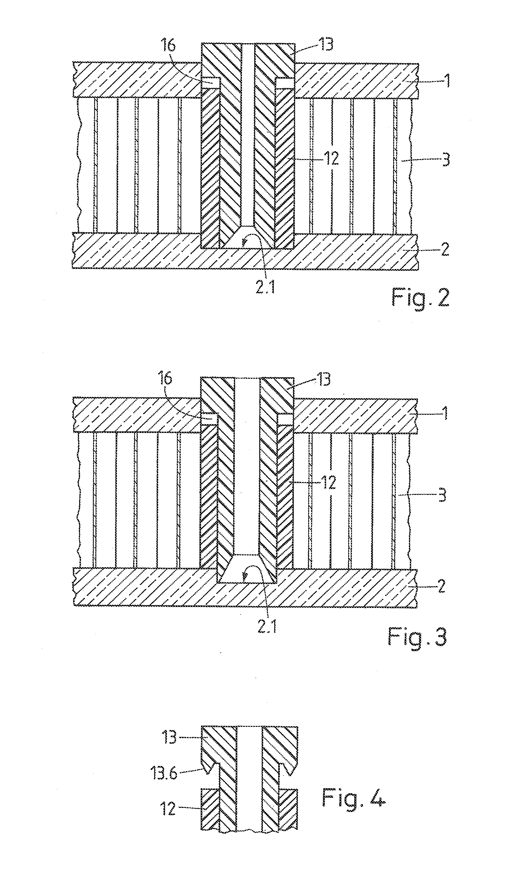
[0052]The lightweight building board of FIG. 1a comprises a first building layer 1, a second building layer 2, and an interlining 3 between the first and second building layer. The first and second building layers may be of identical or of different material compositions. They may for example be of a wood based material, such as a wood composite material like a fiberboard (particle board, medium-density fiberboard, or hardboard) or the like. The building layer thicknesses d1, d2 of the two building layers may be equal or different and may for example be between 1 mm and 15 mm, especially between 2 mm and 10 mm. The distance d1 of the building layers may be chosen within a large range, depending on the needs. Often it is between 20 mm and 50 mm, however, other distances are not excluded, since the distance d1 for most embodiments of the invention is not a critical number.

[0053]The interlining 3 may for example a honeycomb-like structure of cardboard, or alternatively a light insulati...


PUM

PropertyMeasurementUnit
Thicknessaaaaaaaaaa
Mechanical propertiesaaaaaaaaaa
Metallic bondaaaaaaaaaa

Abstract

A connector and a method of anchoring the connector to a first object that includes providing the connector having a sleeve element and a piston element with a shaft portion, providing a through hole in the first object, and inserting the connector through the through hole and until a distal portion of one of the sleeve and / or the piston element rests against the second object. Mechanical oscillations are coupled into the piston element while the piston element is pressed towards the distal side, and thereby liquefying portions a thermoplastic material at an interface portion between the sleeve element and the piston element while a periphery of the interface portion is adjacent the circumferential wall, and causing the liquefied thermoplastic material to flow radially outward from the periphery and into structures of the first object and / or along an inner surface.

Description

FIELD OF THE INVENTION[0001]The invention is in the fields of construction and furniture industry. Especially, it concerns a method of anchoring a connector in a building element, and a connector for being anchored in a building or construction element.BACKGROUND OF THE INVENTION[0002]Lightweight building elements—an important category of such elements are lightweight building boards—comprise two outer, comparably thin building layers, for example of fiberboard or of a metal, and an interlining arranged between the building layer, for example a cardboard honeycomb structure. Lightweight building elements of this kind are mechanically very stable, may look pleasant and have a very low weight.[0003]However, because the building layers are thin and the interlining is not suitable for anchoring a connector—such as a dowel—in it, it is difficult to attach an object to the lightweight building elements other then just by gluing it to the element's surface. Also, in some cases the mechanic...

Claims


Application Information

Patent Timeline
IPC IPC(8): B29C65/08
CPCB29C65/08B29C65/082B29C65/561B29C65/601B29C65/602B29C65/603B29C65/645B29C66/112B29C66/114B29C66/30223B29C66/30326B29C66/474B29C66/53465B29C66/71B29C66/72525B29C66/73921B29C66/7487B29C66/8242B29C66/8322B29L2031/737F16B5/01F16B5/08Y10T403/477B29K2023/06B29K2023/12B29K2025/06B29K2025/08B29K2027/06B29K2033/12B29K2055/02B29K2067/00B29K2069/00B29K2077/00
Inventor COVE, PETER L.VALANCE, WILLIAM R.LEHMANN, MARIOTORRIANI, LAURENT
Owner WOODWELDING
Learn More