Connector

a technology of connecting parts and connectors, applied in the direction of coupling contact members, coupling device connections, two-part coupling devices, etc., can solve the problems of contact failure between the connecting object and the contacts of the connector, the displacement of the first contact protrusion, and the inability to achieve a stable contact state (stable spring), so as to improve the reliability of contact and avoid poor electrical contact.

Inactive Publication Date: 2014-02-13
KYOCERA CONNECTOR PRODS CORP
View PDF1 Cites 11 Cited by
  • Summary
  • Abstract
  • Description
  • Claims
  • Application Information

AI Technical Summary

Benefits of technology

[0013]The present invention provides a connector which can be miniaturized in the insertion direction, of a connecting object into the insulator of the connector, and which makes it possible to achieve a stable contact state even for a connecting object which tends to vary in thickness by making each contact of the connector contact the connecting object securely at two points.
[0022]The second resilient deformable portion of the contact of the connector according to the present invention has a shape so as to extend toward the innermost end of the connecting-object insertion groove from the first contact protrusion and thereafter extending back toward the first contact protrusion rather than a shape that flatly extends toward the innermost end of the connecting-object insertion groove from the first contact protrusion, and accordingly, a large spring length of the second resilient deformable portion can be achieved. This improves the followability of the second resilient deformable portion with respect to the connecting object. Moreover, since the distance from the first contact protrusion to the second contact protrusion (in the insertion / removal direction of the connecting object) is short, even though the spring length of the second resilient deformable portion is large, the amount of deviation of the displacement of the second contact protrusion from a predetermined value (design value) does not become great even if the first contact protrusion is displaced in the contacting direction thereof by a greater amount than a predetermined value (design value) when the connecting object is inserted into the insulator. Therefore, the second contact protrusion is less susceptible to displacements of the first contact protrusion, and accordingly, when the first contact protrusion comes into contact with the trace of the circuit pattern, there is little possibility of the second contact protrusion being deformed to a position where it becomes in non-contact with the trace of the circuit pattern.
[0023]Therefore, the possibility of the contact condition between each of the first contact protrusion and the second contact protrusion and the trace of the circuit pattern becoming unstable is low, and each of the first contact protrusion and the second contact protrusion can be made to contact securely with the trace of the circuit pattern.
[0025]Additionally, since the second contact protrusion comes into contact with a cleaned portion of the trace of the circuit pattern, the possibility of poor electrical contact occurring between the second contact protrusion and the connecting object is low.
[0026]Additionally, since the connecting object and the contact come in contact with each other at two points, even if the contact state of one of the two contact points is temporarily (momentarily) released by vibrations applied to the connector, there is a possibility of the contact state of the other contact point being maintained, which improves contact reliability compared with the case where the connecting object and the contact come in contact with each other at a single point.

Problems solved by technology

However, since various minute particles (e.g., minute dust particles) are present in the interior of vehicles, minute particles may enter the inside of vehicle-mounted electronic equipment and adhere to conductive contact lands of the circuit pattern of the connecting object.
If the contact protrusions of the contacts come in contact with the contact lands of the circuit board with minute dust particles adhered to the contact lands, minute dust particles get caught in between the contact lands and the contact protrusions, which may cause contact failure between the connecting object and the contacts of the connector.
However, since FPCs and FFCs, for instance, tend to vary in thickness due to problems in manufacturing, sometimes the amount of displacement of the first contact protrusion becomes slightly greater than a predetermined value (design value) when an FPC or FFC is inserted into the insulator of the connector.
In addition, if the position of the second contact protrusion in an initial state is set to be far closer to the connecting object for the purpose of making the second contact protrusion contact the circuit pattern with stability, the following problems may arise: the spring force of a portion of the contact which is positioned closer to the base end (on the opposite side from the second contact protrusion) than the first contact protrusion may decrease, or the first contact protrusion may be spaced from the circuit pattern.
Accordingly, it has been extremely difficult to achieve a stable contact state (stable spring force) between the thick connecting object and each contact of the connector by making both the first and second contact protrusions of each contact come into contact securely with the connecting object.

Method used


Image

  • Connector
  • Connector
  • Connector

Examples


Embodiment Construction

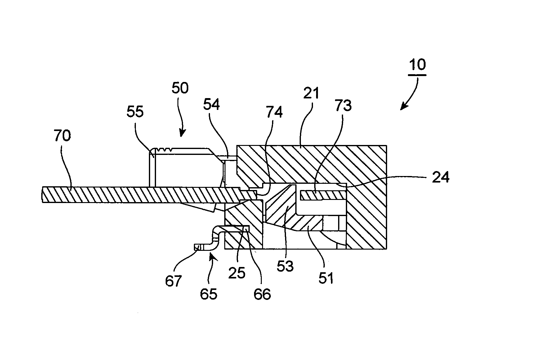
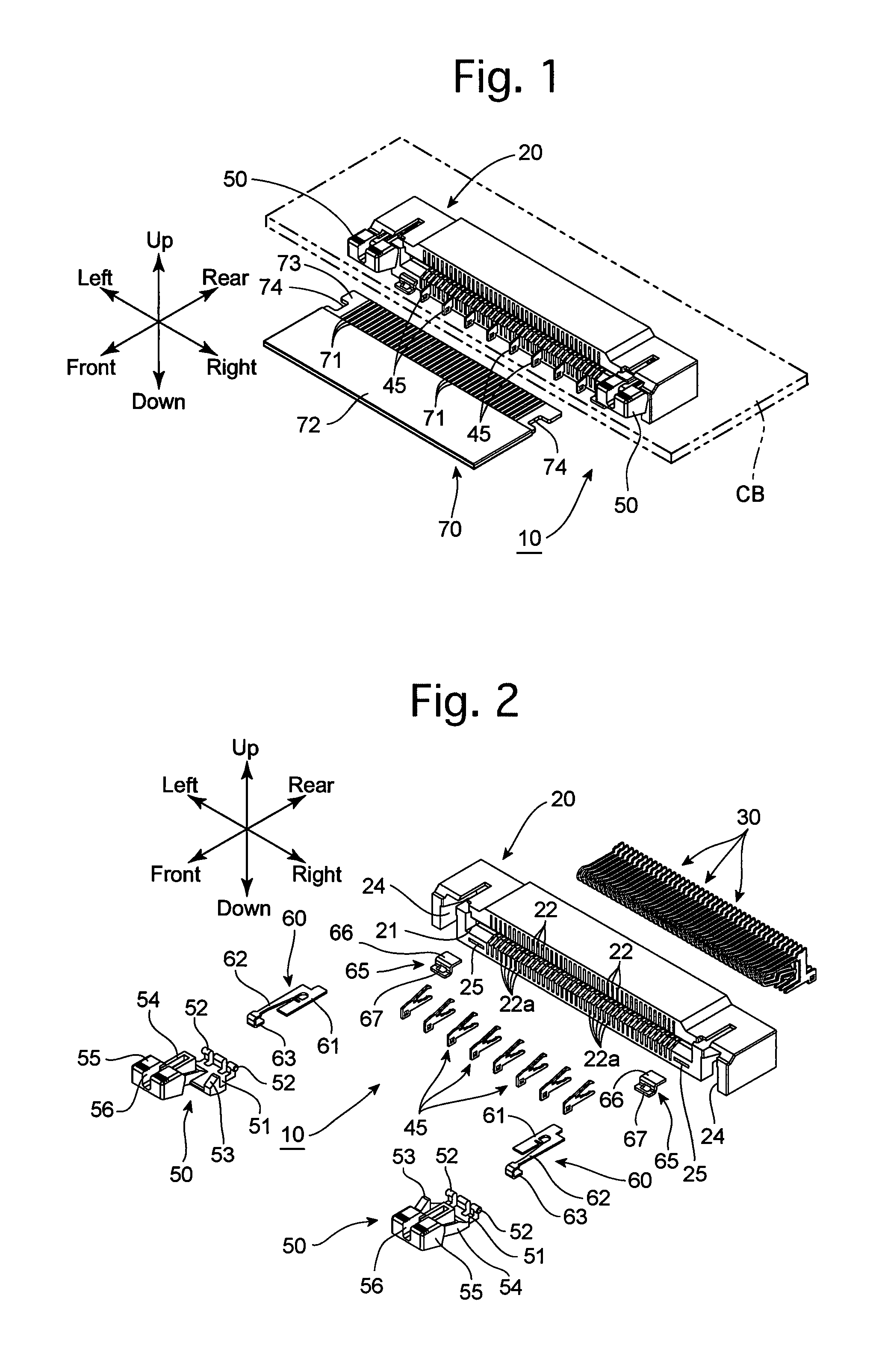
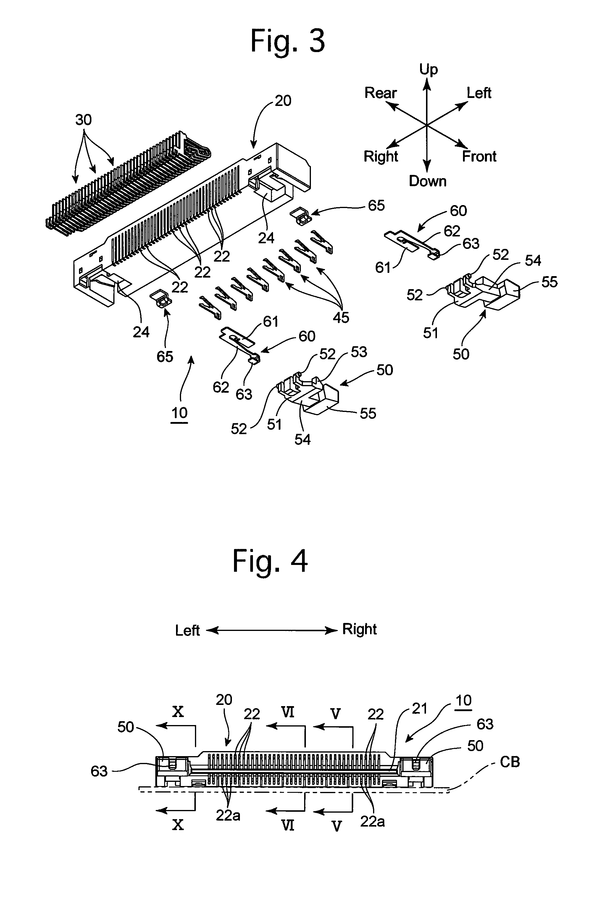
[0041]An embodiment of a connector according to the present invention will be hereinafter discussed with reference to FIGS. 1 through 13. In the following descriptions, forward and rearward directions, leftward and rightward directions, and upward and downward directions of the connector 10 are determined with reference to the directions of the double-headed arrows shown in the drawings.

[0042]The connector 10 is applicable to, e.g., a car navigation system which is installed in or on an instrument panel provided on the front of a vehicle interior, or a multifunctional printer in which a copier and a facsimile are incorporated. The connector 10 is provided with an insulator 20, forty signal contacts 30, eight ground contacts 45, two lock members 50, two lock biasing springs 60 and two fixing brackets 65, which constitute major elements of the connector 10.

[0043]The insulator 20 is formed from electrical-insulative and heat-resistant synthetic resin by injection molding. The insulator...


PUM


Abstract

A connector includes an insulator having a connecting-object insertion groove and at least one contact supported by the insulator to be contactable with a trace of a circuit pattern formed on a connecting object. The contact includes a first resilient deformable portion, a first contact protrusion protruding from the first resilient deformable portion and contacting the trace, a second resilient deformable portion extending toward the innermost end of the connecting-object insertion groove from the first contact protrusion and thereafter extending back toward the first contact protrusion, and a second contact protrusion protruding from the second resilient deformable portion, positioned closer to the innermost end of the connecting-object insertion groove than the first contact protrusion, and contacting a portion of the trace at a position closer to the innermost end than that at which the first contact protrusion contacts.

Description

CROSS REFERENCE TO RELATED APPLICATION[0001]The present invention is related to and claims priority of the following co-pending application, namely, Japanese Patent Application No. 2012-174611 filed on Aug. 7, 2012, herein incorporated by reference in its entirety.FIELD OF THE INVENTION[0002]The present invention relates to a connector capable of being connected to a thin plate-shaped connecting object such as an FPC or FFC.BACKGROUND OF THE INVENTION[0003]Japanese Unexamined Patent Publication No. 2010-3590 discloses an example of a connector capable of being connected to a thin plate-shaped connecting object (such as an FPC or FFC). This connector is provided with an insulator mounted on a circuit board and a plurality of contacts arranged and fixed to the insulator. The insulator is provided with an insertion groove into which the connecting object is insertable, and from which the connecting object is removable, and the plurality of contacts are connected to the aforementioned c...

Claims


Application Information

Patent Timeline
Patent Type & Authority Applications(United States)
IPC IPC(8): H01R13/05
CPCH01R13/05H01R12/774H01R12/79H01R13/2492H01R12/88
Inventor FUJII, YOSHIHARU
Owner KYOCERA CONNECTOR PRODS CORP
Why Eureka
Try Eureka