
Reciprocating sealing device

A reciprocating motion and sealing device technology, which is applied to the sealing of the engine, engine components, springs, etc., can solve the problems of unfavorable wedge shape maintenance, oil leakage, internal pressure rise, etc., to reduce deformation, prevent oil leakage, and improve The effect of tightness

Inactive Publication Date: 2014-08-13
NOK CORP
View PDF8 Cites 2 Cited by
  • Summary
  • Abstract
  • Description
  • Claims
  • Application Information

AI Technical Summary

Problems solved by technology

[0007] (2) The portion that cannot be absorbed by the deformation of the gasket 62 causes an increase in internal pressure
[0010] (5) According to the items and configurations of (1) to (4) above, when high-frequency vibration input is used and high-viscosity oil is used, a large amount of oil leakage may occur
[0013] (a) In the conventional invention, since deformation occurs from the lip, it is disadvantageous in maintaining the wedge shape

Method used


Image

  • Reciprocating sealing device
  • Reciprocating sealing device
  • Reciprocating sealing device

Examples


Embodiment Construction

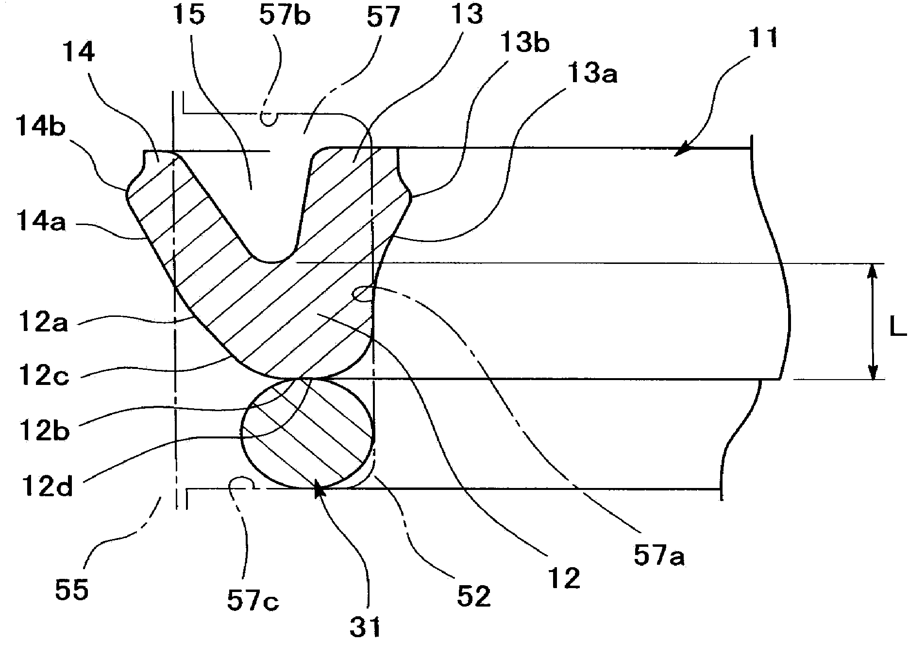
[0066] Hereinafter, embodiments of the present invention will be described based on the drawings.

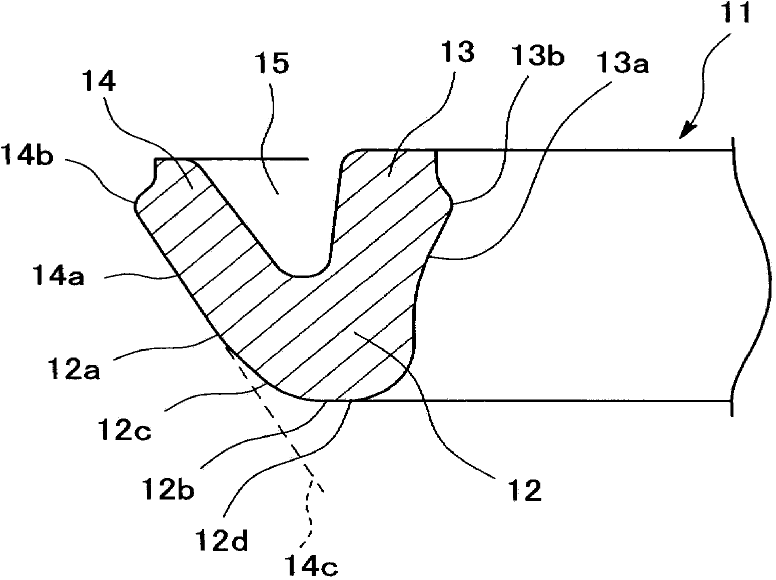
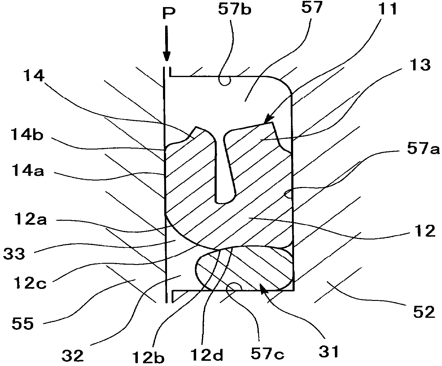
[0067] figure 1 The cross-section of the main part of the gasket 11 and the gasket 31 included in the sealing device according to the embodiment of the present invention is shown, and the gasket 11 and the gasket 31 are attached to, for example, the above-mentioned Figure 6 The annular mounting groove 57 provided on the outer peripheral surface of the shock absorber shaft 52 in the shock absorber mechanism 51 constitutes a sealing device for reciprocating motion (axial reciprocating motion). As described above, the damper mechanism 51 is composed of a damper shaft (one component in the technical solution of the present invention) 52 provided with a piston 53 having an orifice 54 at the front end, and a damper elastically supported by a spring unit 56 . The shock absorber case (the other part in the technical solution of the present invention) 55 is combined, and is assembled b...


PUM


Abstract

Provided is a reciprocating sealing device shaped so that volume absorbing performance is improved, preventing full-surface contact of the packing from readily occurring even when there is an increase in internal pressure, and therefore an excellent sealing performance can be obtained. In order to achieve this purpose, the reciprocating sealing device is a sealing device in which a packing is mounted on a mounting groove provided to one of two members that perform a reciprocating motion relative to each other and the packing is brought into intimate contact with the other member to obtain a seal between the two members. The packing is provided with an annular base part, a stationary-side lip, and a sliding-side lip. A pack ring having a lower hardness than that of the packing is interposed between the annular base part and the groove side surface of the mounting groove. A pack ring forms a space region between the pack ring and the other member. The annular base part is shaped so that the heel part has an arc-shaped or tapered cross-section and the annular base part does not protrude beyond an extension line of a peripheral surface of the sliding-side lip in a free state. The edge surface of the annular base part is provided with a flat part within the range at which contact is made with the pack ring.

Description

technical field [0001] The invention relates to a sealing device related to sealing technology. More specifically, the present invention relates to a sealing device for reciprocating motion. The sealing device of the present invention is used, for example, in a shock absorber mechanism for automobiles, or in other shock absorber mechanisms. Background technique [0002] Previously, it was known that there were Figure 6 The shock absorber mechanism 51 shown in FIG. 10 is equipped with a sealing device 61 in order to seal the oil O sealed inside the shock absorber mechanism 51 . [0003] The illustrated damper mechanism 51 is composed of a damper shaft 52 having a piston 53 with an orifice 54 at its tip, and a damper housing 55 elastically supported by a spring unit 56 . A sealing device 61 is installed between the damper shaft 52 and the damper housing 55 in order to seal the oil O sealed inside the damper housing 55 . In addition, a sealing piece 71 is attached to a part...

Claims


Application Information

Patent Timeline
IPC IPC(8): F16J15/18F16F9/36F16J15/32F16J15/3232F16J15/3236
CPCF16J15/56F16J15/3236F16J15/18F16J15/32F16F9/36F16J15/3204F16J15/20
Inventor 神保一宪冈田裕纪荒木亨
Owner NOK CORP
Learn More