
Staged Locking of Surgical Screw Assembly

Active Publication Date: 2014-02-13
SPINECRAFT
View PDF2 Cites 18 Cited by
  • Summary
  • Abstract
  • Description
  • Claims
  • Application Information

AI Technical Summary

Benefits of technology

The patent describes a surgical screw assembly that includes a fastener and a tulip for spine procedures. The assembly has locking enhancement features that securely lock into the head of the fastener to prevent relative movement between them. This ensures that the tulip and vertebra can be securely locked in place during the procedure. The method of using the assembly involves implanting the fastener into a vertebra, attaching a support member, and applying a compression force to lock the assembly. The technical effect of the invention is to provide a reliable and secure fastener for spine procedures that allows for secure locking of the spine and prevention of rotation.

Problems solved by technology

Due to the complex curvature of the spine, as well as irregularities of the same that often need to be treated, it is often difficult to align a rod or plate with all of the implants / fasteners fixed to the various vertebrae to be connected via the rod or plate.

Method used


Image

  • Staged Locking of Surgical Screw Assembly
  • Staged Locking of Surgical Screw Assembly
  • Staged Locking of Surgical Screw Assembly

Examples


Embodiment Construction

[0154]Before the present assemblies, components and systems are described, it is to be understood that this invention is not limited to particular embodiments described, as such may, of course, vary. It is also to be understood that the terminology used herein is for the purpose of describing particular embodiments only, and is not intended to be limiting, since the scope of the present invention will be limited only by the appended claims.

[0155]Where a range of values is provided, it is understood that each intervening value, to the tenth of the unit of the lower limit unless the context clearly dictates otherwise, between the upper and lower limits of that range is also specifically disclosed. Each smaller range between any stated value or intervening value in a stated range and any other stated or intervening value in that stated range is encompassed within the invention. The upper and lower limits of these smaller ranges may independently be included or excluded in the range, an...


PUM


Abstract

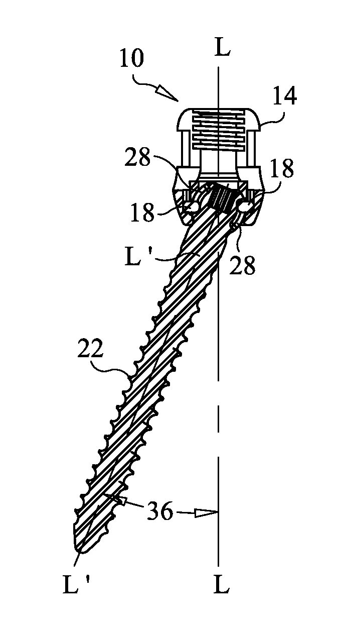
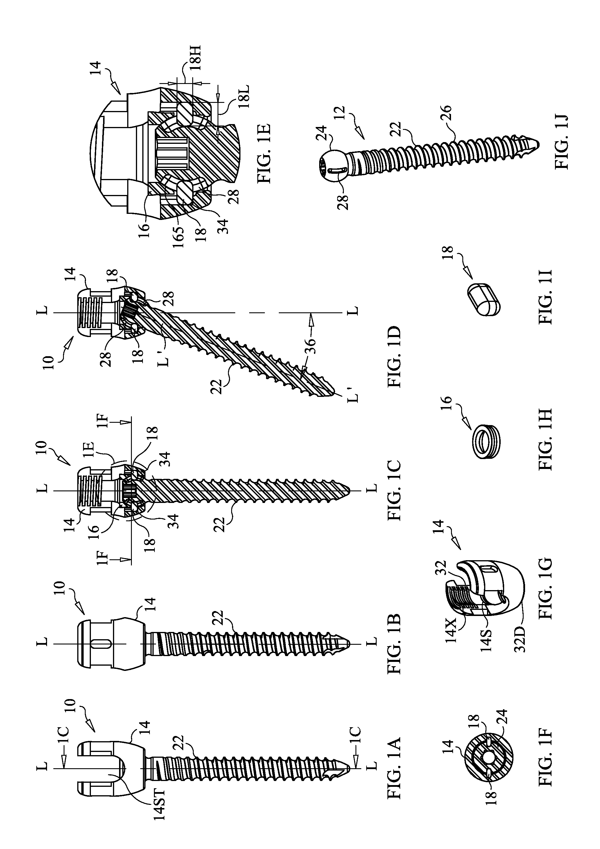
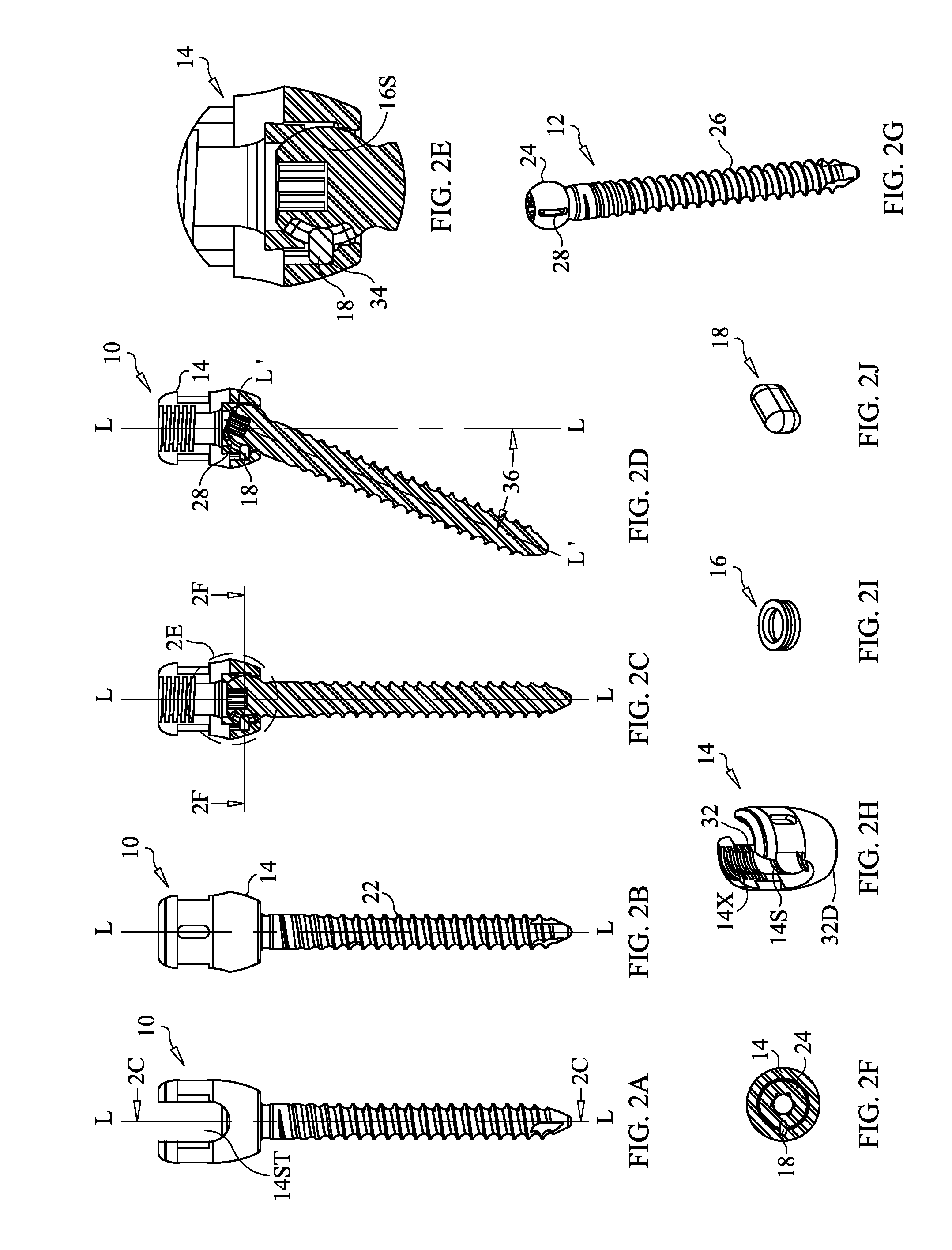
A surgical screw assembly including: a fastener including an elongate shaft having a proximal end and a distal end and a head at the proximal end. A tulip having a an internal bearing surface is provided. A distal end of the tulip has a bore therethrough defining the internal bearing surface. Locking enhancement features are configured to cooperate with the head, such that, in an unlocked configuration, the head is movable relative to the tulip; in a provisionally locked configuration, the locking enhancement features engage the head with a first polyaxial grip strength; and in a finally locked configuration, the locking enhancement features engage the head with a second polyaxial grip strength greater than the first polyaxial grip strength.

Description

CROSS-REFERENCE[0001]This application is a continuation-in-part application of co-pending application Ser. No. 13 / 570,374, filed Aug. 9, 2012 and titled “Uniplanar Surgical Screw Assembly”, which is hereby incorporated herein, in its entirety, by reference thereto, and to which application we claim priority under 35 USC §120. This application also references application Ser. No. ______ (Attorney's Docket No. SCFT-006CIP) filed concurrently herewith and titled “Locking Force Augmentation Features for Polyaxial Screw Assembly”, which application is hereby incorporated herein, it its entirety, by reference thereto.FIELD OF THE INVENTION[0002]The present invention relates to the field of orthopedic surgery, in particular to devices, systems and assemblies for stabilizing and / or fixing bones and / or joints in a patient. More particularly, the present invention relates to polyaxial attachment assemblies including mechanisms for locking the same.BACKGROUND OF THE INVENTION[0003]The fixation...

Claims


Application Information

Patent Timeline
IPC IPC(8): A61B17/86A61B17/88A61B17/70
CPCA61B17/8605A61B17/88A61B17/7002A61B17/7037A61B2090/037A61B17/7034A61B17/7038A61B17/7079A61B17/70A61B17/7049A61B17/708A61B17/7085A61B17/7091A61B17/7032A61B17/7035A61B2017/681A61B90/03
Inventor ASAAD, WAGDY W.IBRAHIM, KAMALVARGHESE, JAYSON
Owner SPINECRAFT
Learn More