Apparatus and method for extruding a multilayered structure

a multi-layered structure and apparatus technology, applied in dough shaping, manufacturing tools, food shaping, etc., can solve the problems of static coextrusion process not being suitable for producing articles, and dynamic die assembly being relatively complex in construction, so as to enhance the shearing action of polymer material produced by the rotation of the shearing rod, the effect of reducing the flow area and enhancing the shearing action

Inactive Publication Date: 2007-04-19
CRYOVAC ILLC
View PDF3 Cites 1 Cited by
  • Summary
  • Abstract
  • Description
  • Claims
  • Application Information

AI Technical Summary

Benefits of technology

[0011] Advantageously, the shearing action of the polymer material produced by the rotation of the shearing rod is enhanced by narrowing the annular space in the region where the second melt streams lead into the annular space. For example, the shearing rod can include a portion of relatively greater diameter than other portions of the shearing rod so that the annular space between the larger-diameter portion and the inner surface of the housing bore is reduced in flow area. The passage(s) for the second melt stream(s) can lead into the annular space at a location proximate the larger-diameter portion of the shearing rod. Alternatively, the reduction in flow area can be accomplished by a reduction in the diameter of the housing bore at one location, or by a combination of increased rod diameter and reduced bore diameter at one location.

Problems solved by technology

The splitting and recombining of melt streams require space and time to accomplish.
Accordingly, the static coextrusion process is not suitable for producing articles having a large number of very thin layers or “microlayers”.
Often these dynamic die assemblies are relatively complex in construction, tend to have reliability problems, and can be prone to leaking.
Often these static die assemblies are relatively complex in construction and are fixed to a certain number of layers per assembly.

Method used


Image

  • Apparatus and method for extruding a multilayered structure
  • Apparatus and method for extruding a multilayered structure
  • Apparatus and method for extruding a multilayered structure

Examples


first embodiment

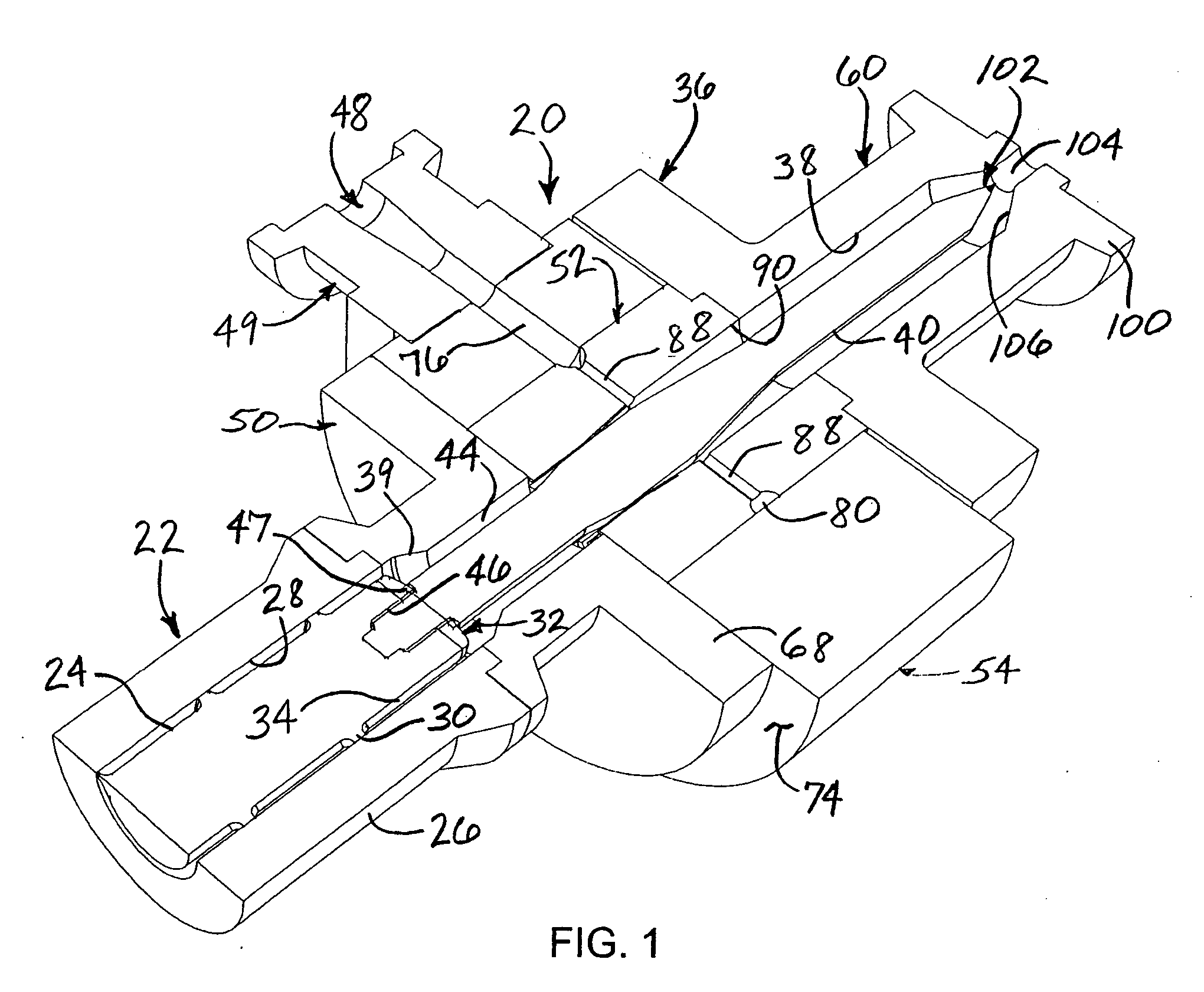
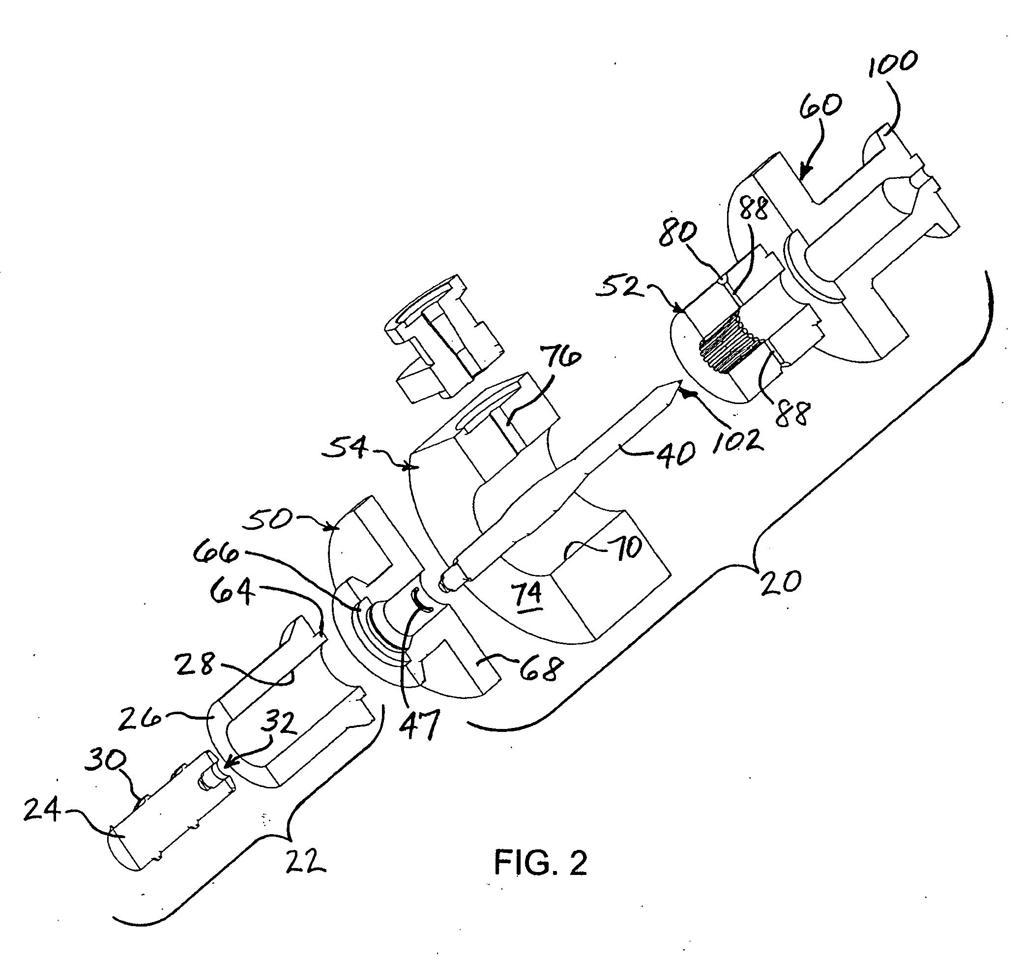
[0024] With reference to FIGS. 1 through 3, an apparatus 20 in accordance with the invention is shown assembled with an extruder 22 with which the apparatus 20 is configured to be used. The extruder comprises an extruder screw 24 that is rotatable within a tubular extruder barrel or housing 26. The extruder housing 26 has a cylindrical bore 28 (also referred to herein as a first portion of the bore) extending therethrough. The screw 24 has a helical screw thread 30 projecting from its outer surface and extending helically along a length of the screw. The thread 30 terminates at an end portion 32 of the screw. The end portion 32 of the extruder screw is disposed in the bore 28 of the housing 26 so as to define a first annular space 34 between the outer surface of the extruder screw 24 and an inner surface of the bore 28. The screw thread cooperates with the bore such that rotation of the extruder screw advances a first melt stream of polymer material in a generally helical fashion al...

second embodiment

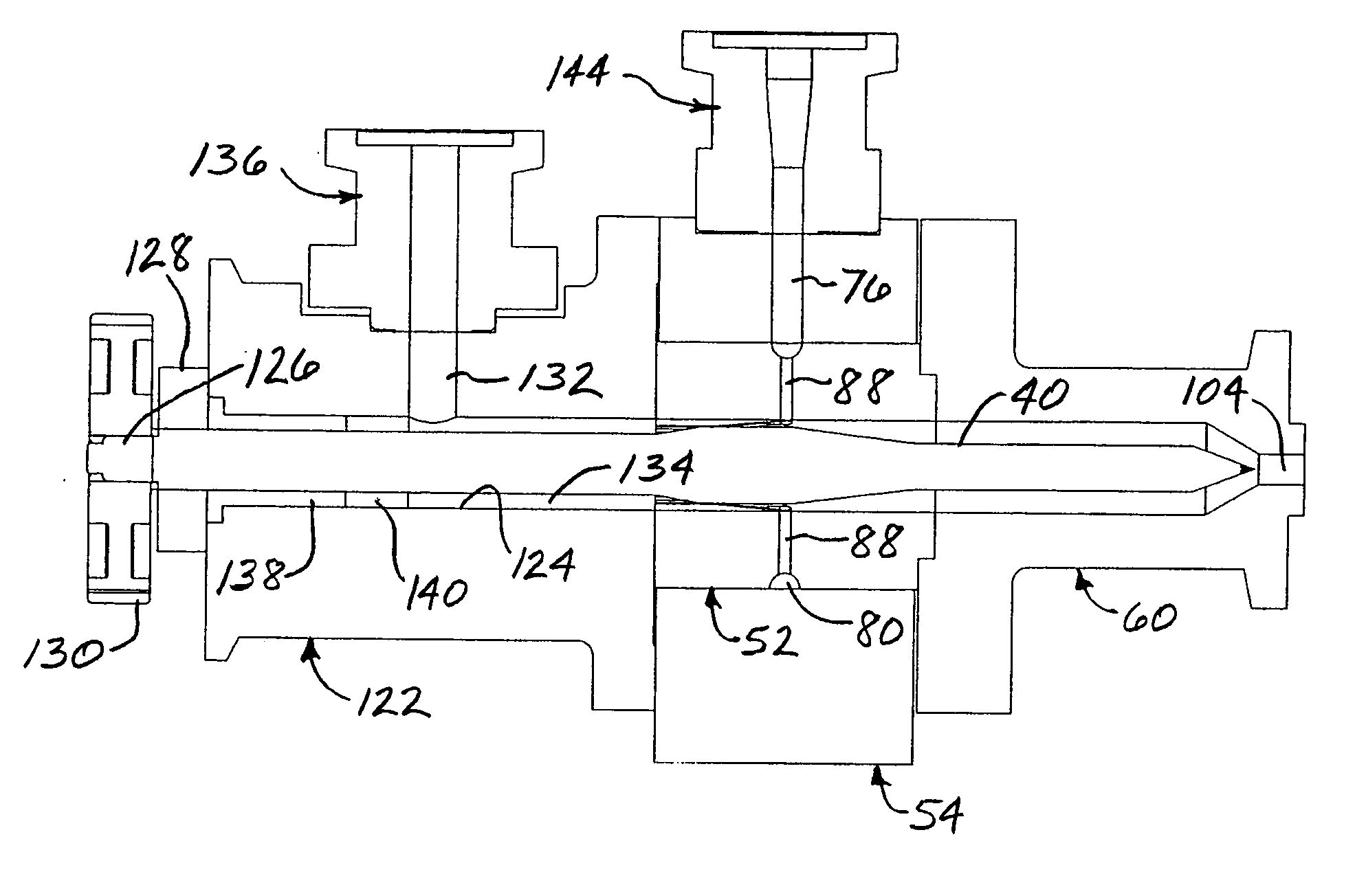
[0035] the invention is depicted in FIGS. 5 and 6. The apparatus 120 illustrated in these figures is generally similar in many respects to the apparatus 20 described above. The distributor 52, distributor housing 54, and feed block connector 60 are substantially as described above. Accordingly, the present description focuses upon the significant differences. The primary difference between the apparatus 120 and the previously described embodiment is that the apparatus 120 employs an independent drive arrangement for rotating the shearing rod 40 rather than driving the rod with an extruder screw. A housing member 122 is connected to the upstream end of the distributor housing 54. The housing member 122 defines a generally cylindrical bore 124 therethrough. The shearing rod 40 extends through the bore 124 and an upstream end 126 of the rod projects out from the bore 124 at the upstream end of the housing member. The end 126 of the rod is supported by a bearing 128 affixed to the housi...


PUM

PropertyMeasurementUnit
diameteraaaaaaaaaa
flow areaaaaaaaaaaa
meltaaaaaaaaaa

Abstract

An apparatus and method for extruding a multilayered article employs a shearing rod connected to the end of an extruder screw. The shearing rod is rotated along with the extruder screw and shears the polymer materials being advanced along an annular space between the shearing rod and the inner surface of a bore in a housing. A first melt stream of polymer material is advanced by the extruder screw into the annular space. A second melt stream of polymer material is fed (e.g., from a second extruder) through a passage in the housing into the annular space to join with the first melt stream therein. The rotation of the shearing rod shears the melt streams and swirls them together to produce a multiplicity of layers of the polymer materials.

Description

BACKGROUND OF THE INVENTION [0001] The present invention generally relates to coextrusion of polymer articles from two or more melt streams comprising one or more types of polymers. The invention more particularly relates to coextrusion of polymer articles having a multiplicity of layers or microlayers of the same or different polymer materials. [0002] In the production of articles such as polymer films, it has been recognized that improvements in one or more properties of a polymer article can be achieved by manufacturing the article as a layered structure having two or more layers of the same or different polymer materials. For example, one polymer material may be good in property A but poor in property B, while another polymer material may be weak in property A but may excel in property B. An article formed with layers of both polymer materials can achieve good performance in both properties A and B. [0003] It has also been found that a laminar morphology can be advantageous even...

Claims


Application Information

Patent Timeline
Patent Type & Authority Applications(United States)
IPC IPC(8): B29C47/26B29C48/08B29C48/21B29C48/335B29C48/495B29C48/52B29C48/67
CPCB29C47/0023B29C47/003B29C47/065B29C47/261B29C47/56B29C47/6012B29C48/09B29C48/12B29C48/21B29C48/336B29C48/52B29C48/08B29C48/495
Inventor PRITCHETT, TIMPEAVEY, JENNIFER
Owner CRYOVAC ILLC
Why Eureka
Try Eureka