Float type drain trap

a technology of float type and drain trap, which is applied in steam traps, thin material handling, transportation and packaging, etc., can solve the problems of difficult to obtain snap action of pilot valve, complicating construction, and inability to prevent penetration, so as to reduce the trouble of pilot valve, reduce the bore diameter of pilot valve, and reduce the float size

Inactive Publication Date: 2007-01-11
NIPPON SEIKI CO LTD
View PDF4 Cites 7 Cited by
  • Summary
  • Abstract
  • Description
  • Claims
  • Application Information

AI Technical Summary

Benefits of technology

[0012] According to the float type drain trap of the present invention, it becomes possible to indirectly operate the pilot valve with a magnetic force acting between the permanent magnet provided on the pilot valve and the permanent magnet provided on the float. Moreover, because the repulsion of the two permanent magnets is proportional to the amount of lifting of the float, the repulsion of the magnets gradually increases as the float goes up and, when that repulsion exceeds the back pressure acting on the pilot valve, the pilot valve opens instantly and, in addition, the float further goes up because the back pressure decreases and the load on the float lessens with the opening of the pilot valve, thus enabling to provide a function of snap action for fully opening the pilot valve accurately, to thereby perform stable discharge of drain in a wide operating pressure range from low pressure to high pressure.
[0013] Furthermore, this float type drain trap, which indirectly operates the pilot valve with a magnetic force, enables to provide an orifice and a filter in the inlet route of pilot air pressure in the upstream of the pilot valve, to thereby prevent penetration of harmful foreign matters into the pilot valve and reduce troubles of the pilot valve due to penetration of foreign matters.
[0014] And, by disposing the orifice on the upstream side of the pilot valve, it becomes possible to reduce the bore diameter of the pilot valve to a size about the same as that of the orifice, thus reducing the float size.
[0015] Still more, with a conventional float type drain trap, the control system of pilot air pressure is restricted and there is no choice but adopt a spool valve system as system of the drain valve, and this results in damaging of the drain valve in short period in some cases because the stroke of the piston and of the drain valve becomes longer in the spool valve system. With the float type drain trap of the present invention, however, a wider choice of pilot air pressure control system enables to adopt a poppet valve system, and a poppet valve system can reduce troubles of the drain valve thanks to simple valve structure and possibility of shortening of stroke.
[0016] And, while a conventional float type drain trap required a mechanism for connecting between the pilot valve and the float and troubles were liable to be produced because of a failure of this mechanism, the float type drain trap of the present invention, which does not require any such mechanism, can eliminate troubles of this kind.

Problems solved by technology

However, a problem with this system is that the mechanism for transmitting the motions of the float 6 to the pilot valve 7 is exposed and it is impossible to provide a filter 10 in this portion, and this makes it impossible to prevent penetration of harmful foreign matters into the pilot valve 7, frequently producing troubles such as operating error due to clogging of the pilot valve 7, or air leak due to biting of foreign matters in the pilot valve 7, etc.
Moreover, with a conventional float type drain trap, it was rather difficult to obtain snap actions of the pilot valve 7, because of the construction in which the pilot valve 7 is operated directly with the motions of the float 6, presenting a problem of half-open state of the pilot valve 7 or the drain valve 3.
However, this complicates the construction, frequently presenting troubles due to problems in the connecting portion.

Method used


Image

  • Float type drain trap
  • Float type drain trap
  • Float type drain trap

Examples


Embodiment Construction

[0020] An embodiment of the float type drain trap according to the present invention will be explained hereafter, with reference to drawings.

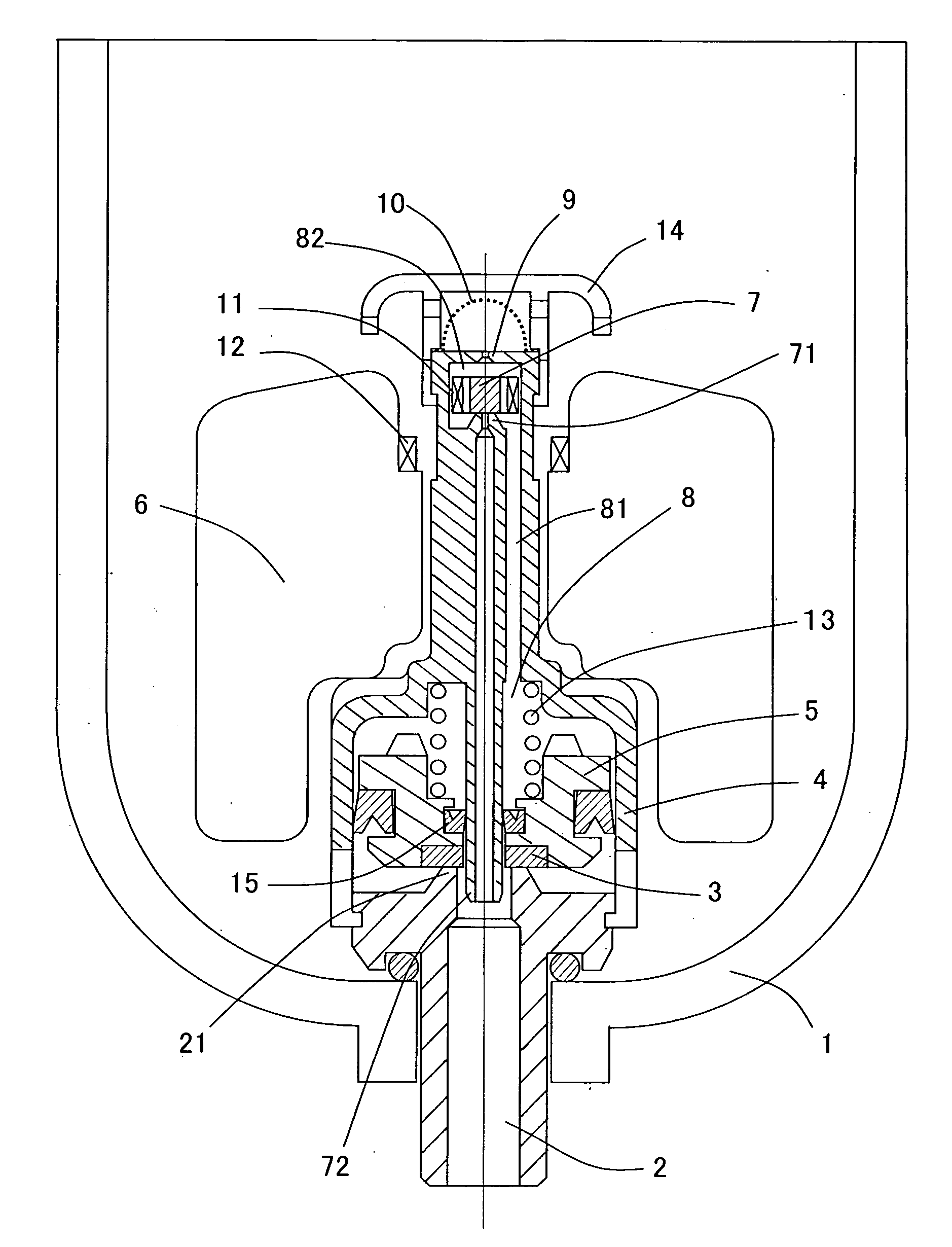
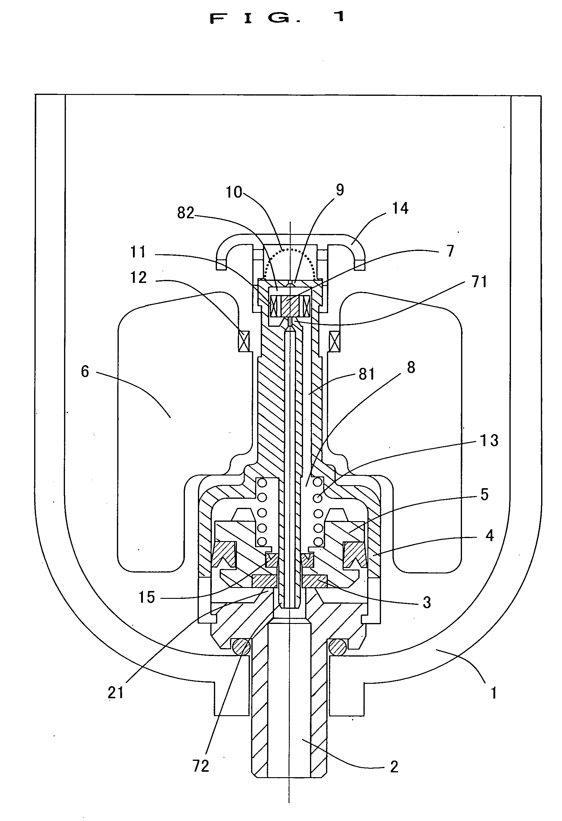
[0021]FIG. 1 shows an embodiment of the float type drain trap according to the present invention.

[0022] This float type drain trap is realized by providing a drain valve 3 for opening / closing the discharge port 2 of a drain case 1 on a piston 5 stored in a cylinder 4, and also providing a pilot valve mechanism for opening the drain valve 3 by making pilot air pressure act on the piston 5, to perform opening / closing of the pilot valve 7 of said pilot valve mechanism with up-down motions of a float 6 disposed on the outside of said cylinder 4.

[0023] And, in this float type drain trap, said pilot valve mechanism is constructed by comprising a pilot valve 7, disposed in part of the pilot chamber 8 and putting the pilot chamber 8 in communication with the outside of the drain case 1, an orifice 9, formed on the upstream side of the pilot valve 7 ...


PUM


Abstract

The present invention provided a float type drain trap capable of preventing penetration of foreign matters into the pilot valve to eliminate troubles caused with penetration of foreign matters, furnishing the pilot valve operation with stability and function of snap action, and reducing the bore diameter of the pilot valve to make the float as small as possible.
The pilot valve mechanism is constructed by comprising a pilot valve 7, disposed in part of the pilot chamber 8 and putting the pilot chamber 8 in communication with the outside of the drain case 1, an orifice 9, formed on the upstream side of the pilot valve 7 and putting the pilot chamber 8 in communication with the inside of the drain case 1, and a microfilter 10 provided on the orifice 9, and a permanent magnet 11 is provided on said pilot valve 7, while on said float 6 is provided a permanent magnet 12 for operating the pilot valve 7 in repellence to the permanent magnet 11.

Description

BACKGROUND OF THE INVENTION [0001] The present invention concerns a float type drain trap used for automatically discharging the drain contained in compressed air. [0002] A float type drain trap is realized, as shown in FIG. 2 or FIG. 3, by providing, on a piston 5 stored in a cylinder 4, a drain valve 3 for opening / closing the discharge port 2 of a drain case 1 and also providing a pilot valve mechanism for opening the drain valve 3 by making pilot air pressure act on the piston 5, to open / close the pilot valve 7 of said pilot valve mechanism with up-down motions of a float 6 disposed on the outside of said cylinder 4. [0003] In that case, a conventional float type drain trap as shown in FIG. 2 or FIG. 3 adopts a system of directly opening / closing the pilot valve 7 with the buoyancy of the float 6 in the majority of cases. However, a problem with this system is that the mechanism for transmitting the motions of the float 6 to the pilot valve 7 is exposed and it is impossible to pro...

Claims


Application Information

Patent Timeline
Patent Type & Authority Applications(United States)
IPC IPC(8): F16T1/20
CPCF16T1/20Y10T137/3077
Inventor YAMAMOTO, HIROSHI
Owner NIPPON SEIKI CO LTD
Why Eureka
Try Eureka