Composite steering rack

a technology of steering racks and composite materials, applied in the direction of transportation and packaging, other domestic objects, gearing, etc., can solve the problems of waste of materials, relatively expensive process, high cost, etc., and achieve the effect of reducing the bore diameter and increasing the wall thickness

Inactive Publication Date: 2007-06-21
BISHOP INNOVATION PTY LTD
View PDF22 Cites 14 Cited by
  • Summary
  • Abstract
  • Description
  • Claims
  • Application Information

AI Technical Summary

Benefits of technology

[0007] In a first aspect the present invention consists of a steering rack for a vehicle rack and pinion steering gear, comprising a first member having a toothed region, attached to a tubular second member, characterized in that said second member has at least one region of increased wall thickness and reduced bore diameter formed by an upsetting operation.

Problems solved by technology

However, the disadvantages of gun drilling are that material is wasted and it is a relatively expensive process.
This method is expensive and time consuming and as such is not suited to high volume production.
Furthermore, the size of teeth that can be produced is limited by the wall thickness of the tube and the method is not suited to producing racks with variable ratio teeth.
A disadvantage of the Honda “Odyssey” rack is that since the tubular shank has a constant wall thickness along its length, the wall must be thick enough to machine this groove on its outside diameter without weakening the rack.
These localized limitations on wall thickness mean that a composite rack having a tubular shank of constant wall thickness cannot fully exploit the weight saving potential of a composite rack.

Method used


Image

  • Composite steering rack
  • Composite steering rack
  • Composite steering rack

Examples


Embodiment Construction

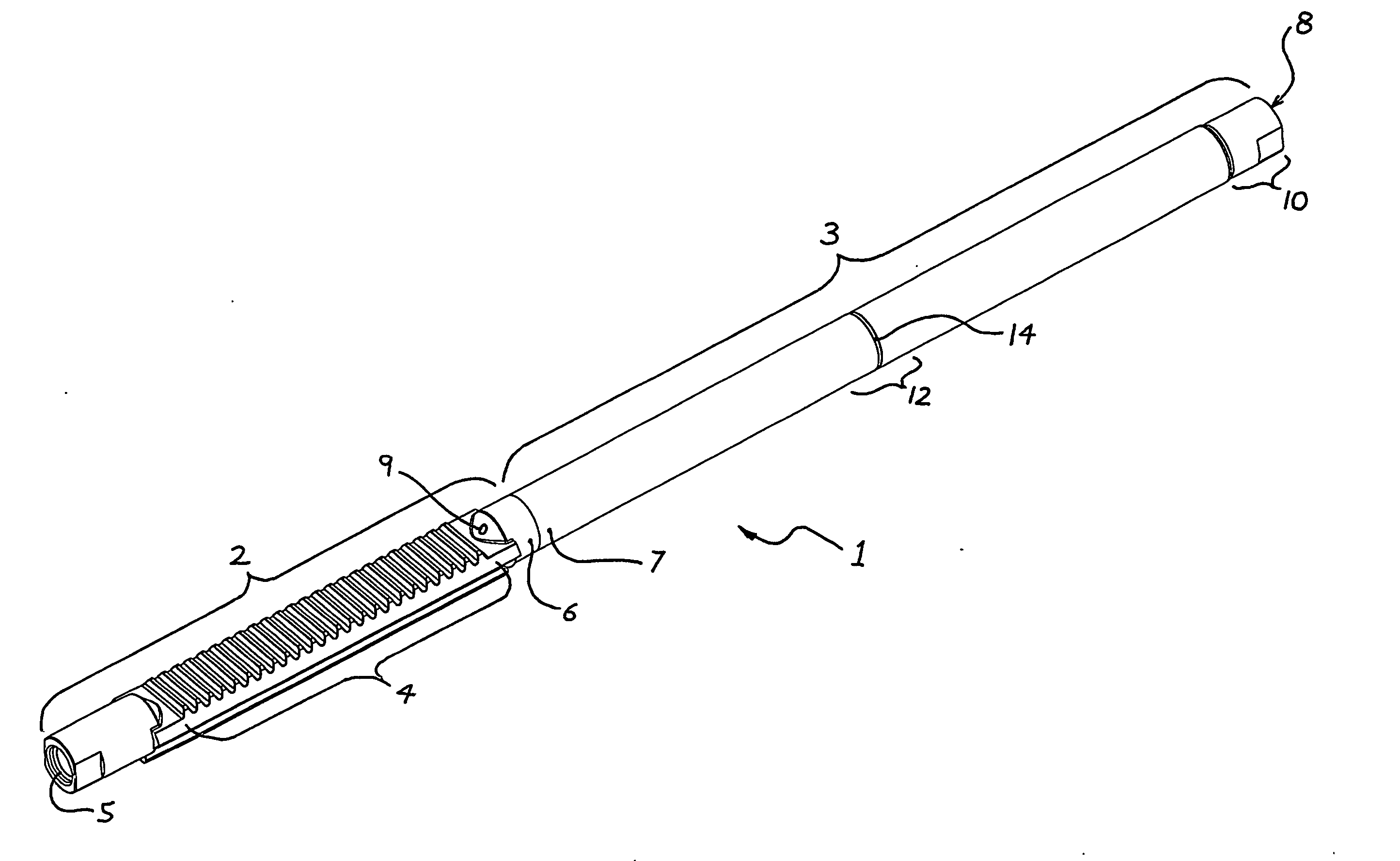
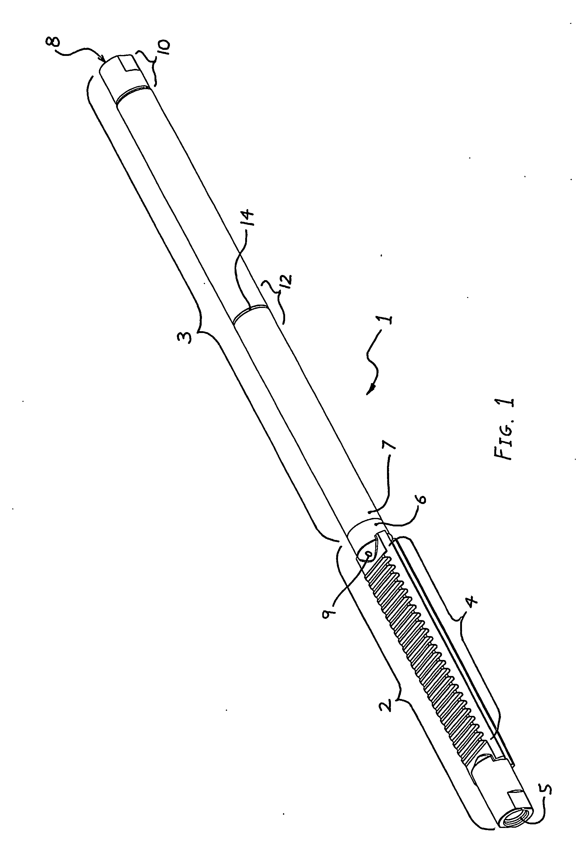
[0026]FIG. 1 depicts a composite steering rack 1 in accordance with the present invention comprising a forged rack tooth member 2 and a tubular shank member 3. Tooth member 2 has a toothed region 4 over a substantial length thereof, a tie rod end 5 with an internal thread for attaching a tie rod, and a joint end 6 at the opposite end thereof.

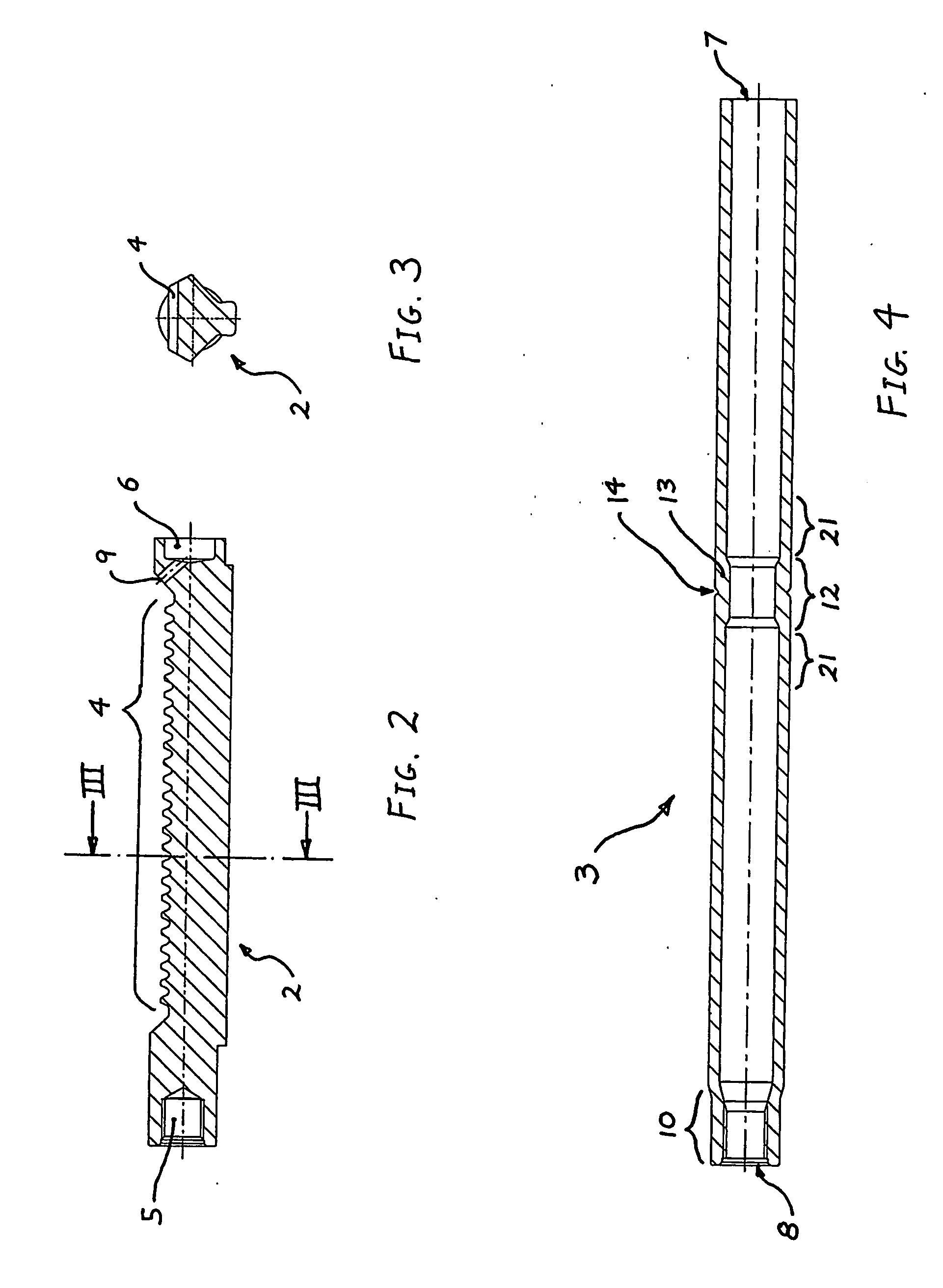
[0027] Tooth member 2 is flashless warm forged from a solid cylindrical blank (not shown) in a die apparatus similar to that disclosed in U.S. Pat. No. 4,571,982 (Bishop) and U.S. Pat. No. 5,862,701 (Bishop et al). Toothed region 4 is forged to net shape and the teeth thereon do not require any further machining. The cross section of toothed region 4 has a ‘Y’ shape as shown in FIG. 3. Once tooth member 2 has been warm forged, toothed region 4 is subsequently induction hardened. The ends of tooth member 2 are left soft to allow for machining to produce tie rod end 5 and joint end 6, as shown in FIG. 2. Joint end 6 is machined to have a protrudi...


PUM

PropertyMeasurementUnit
thicknessaaaaaaaaaa
diameteraaaaaaaaaa
thicknessaaaaaaaaaa

Abstract

A steering rack for a vehicle rack and pinion steering gear and a method of manufacture thereof. The steering rack comprising a first member having a toothed region, attached to a tubular second member. The second member having at least one region of increased wall thickness and reduced bore diameter formed by an upsetting operation.

Description

TECHNICAL FIELD [0001] The present invention relates to steering racks for vehicle rack and pinion steering gears, and more particularly to such racks manufactured by attaching a tubular member to a toothed member. BACKGROUND [0002] Most vehicle steering racks are manufactured from round solid bar stock, with the toothed region broached across the bar near one end. This results in the cross section of the toothed region having a ‘D’ shape and hence these racks are commonly referred to as “D-racks”. The toothed region of such a broached D-rack has significantly less bending strength than the round solid shank extending from it. However, to minimize the weight of the steering rack, it is desirable that the toothed region and the shank have similar bending strength. A common approach to this problem is to gun drill the shank over most of its length resulting in a substantially tubular shank. However, the disadvantages of gun drilling are that material is wasted and it is a relatively e...

Claims


Application Information

Patent Timeline
Patent Type & Authority Applications(United States)
IPC IPC(8): F16H1/18B21K1/76B62D3/12
CPCB21J5/12B21K1/767B21K1/768Y10T74/1515Y10T74/1967Y10T29/49474Y10T74/19819B62D3/126
Inventor ROESKE, KLAUS JUERGEN
Owner BISHOP INNOVATION PTY LTD
Why Eureka
Try Eureka