
Valve assembly of shock absorber

Active Publication Date: 2014-02-20
HL MANDO CORP
View PDF2 Cites 67 Cited by
  • Summary
  • Abstract
  • Description
  • Claims
  • Application Information

AI Technical Summary

Benefits of technology

The present invention addresses the problems in the prior art by providing a valve assembly for a shock absorber that can adjust the attenuation force based on pressure and frequency. Additionally, the valve assembly includes a sub-valve unit to control pressure generated based on speed change.

Problems solved by technology

However, the conventional shock absorber having a frequency sensitive valve device does not have any means for controlling the pressure additionally generated according to the speed change, besides the main valve unit.
Further, although it is necessary to increase the attenuation force in order to stably control the behavior of the vehicle body at a high speed operation in which the piston rod moves at a high speed due to application of an instantaneous large impact, the conventional shock absorber undergoes loss of the attenuation force because the hydraulic fluid is drained through a bypass fluid channel formed at one side of the frequency sensitive valve device in the conventional shock absorber.
Therefore, this conventional shock absorber undergoes loss of the attenuation force through the rotary valve at the time of high speed behavior.

Method used


Image

  • Valve assembly of shock absorber
  • Valve assembly of shock absorber
  • Valve assembly of shock absorber

Examples


embodiments

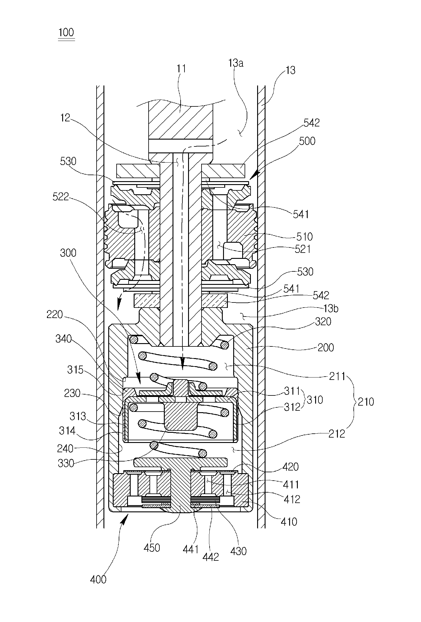
[0040]FIG. 2 is a cross-sectional view of a valve assembly of a shock absorber according to an embodiment of the present invention, which shows an initial installation state of the valve assembly, FIG. 3 is a cross-sectional view showing an operation state of a sub-valve unit according to an embodiment of the present invention, and FIG. 4 is a cross-sectional view showing a state in which a side fluid channel is blocked in response to an instantaneous input of a large shock or a large amplitude behavior, so as to block the operation of the sub-valve unit.

[0041]As shown in FIG. 2, a valve assembly 100 of a shock absorber according to an embodiment of the present invention is assembled with a lower end of a piston rod 11 and includes a frequency sensitive valve unit 300 and a sub-valve unit 400 which are vertically disposed up and down.

[0042]More specifically, the valve assembly 100 of the shock absorber according to the exemplary embodiment of the present invention includes a valve h...


PUM


Abstract

A valve assembly of a shock absorber can achieve both an effect of varying an attenuation force according to a frequency region of vibration or shock transferred to the shock absorber during the driving of an automobile and an effect of varying an attenuation force according to an additional pressure and can increase the attenuation force in response to an instantaneous input of a large amplitude behavior. The valve assembly includes: a valve housing coupled to a piston rod having an orifice hole and a space formed therein, the space having an open lower end to communicate with the orifice hole; a frequency sensitive valve unit including a free piston configured to vertically partition the space; and a sub-valve unit coupled to the lower end of the space, wherein operation of the sub-valve unit is controlled by ascending and descending of the free piston.

Description

BACKGROUND OF THE INVENTION[0001]1. Field of the Invention[0002]The present invention relates to a valve assembly, and more particularly, to a valve assembly of a shock absorber, which can achieve both an effect of varying an attenuation force according to a frequency region of vibration or shock transferred to the shock absorber during the driving of an automobile and an effect of varying an attenuation force according to an additional pressure and can increase the attenuation force in response to an instantaneous input of a large amplitude behavior.[0003]2. Description of the Prior Art[0004]In general, a vehicle continuously receives vibration or a shock from a road surface through the wheels during driving. Thus, a shock absorbing device is provided between the vehicle body and the vehicle axle so as to prevent the shock or vibration from being directly transferred to the vehicle body, thereby improving ride comfort. In addition, the shock absorbing device suppresses the irregula...

Claims


Application Information

Patent Timeline
IPC IPC(8): F16F9/34
CPCF16F9/34F16F9/5126B60G13/06F16F9/32F16F9/49
Inventor KIM, TAE JU
Owner HL MANDO CORP
Features
  • Generate Ideas
  • Intellectual Property
  • Life Sciences
  • Materials
  • Tech Scout
  • Unparalleled Data Quality
  • Higher Quality Content
  • 60% Fewer Hallucinations
Learn More