
Method And Apparatus For For Monitoring Physical Properties

a technology of physical properties and methods, applied in the direction of thermometers, structural/machine measurement, instruments, etc., can solve the problem of short application of the methods and apparatus so described

Inactive Publication Date: 2014-02-20
SMART AUTONOMOUS SOLUTIONS
View PDF4 Cites 10 Cited by
  • Summary
  • Abstract
  • Description
  • Claims
  • Application Information

AI Technical Summary

Benefits of technology

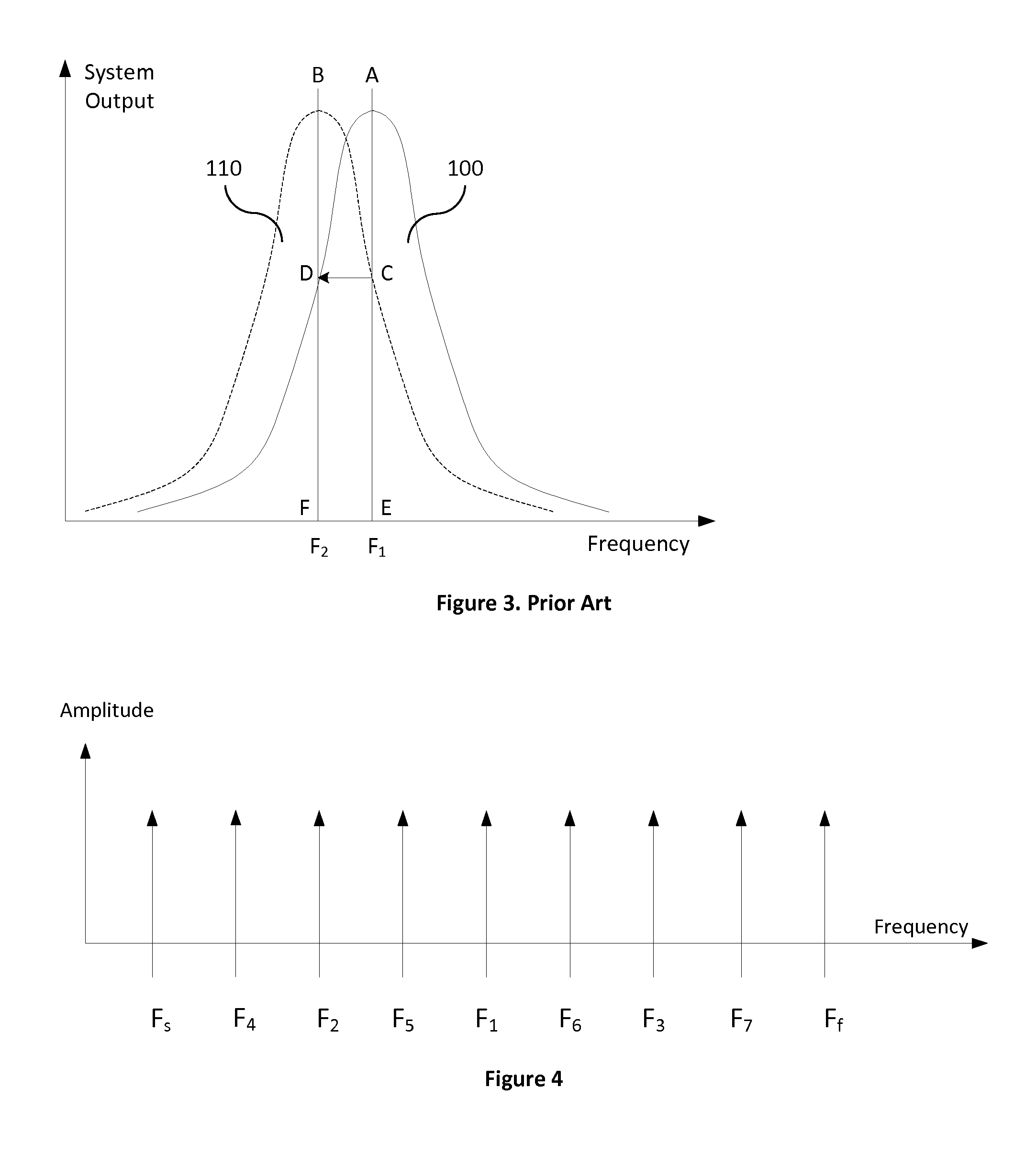
The present invention provides methods and apparatus for extending the range over which microwave cavity sensors can be monitored and detecting the resonant frequency of a microwave cavity sensor. This allows a single receiving device to monitor one or multiple microwave cavity sensors. The invention also provides methods for selecting scanning frequencies adapted for detecting the resonant frequency of a microwave cavity sensor. These technical effects lead to improved accuracy and efficiency in microwave cavity sensor measurements.

Problems solved by technology

While the disclosures provided by Thomson et al. and Fallah-Rad et al. have proven useful, the application of the methods and apparatus so described has been limited by the shortness of range (distance between the sensor and the interrogation apparatus) that is inherent with microwave cavity sensors.

Method used


Image

  • Method And Apparatus For For Monitoring Physical Properties
  • Method And Apparatus For For Monitoring Physical Properties
  • Method And Apparatus For For Monitoring Physical Properties

Examples


Embodiment Construction

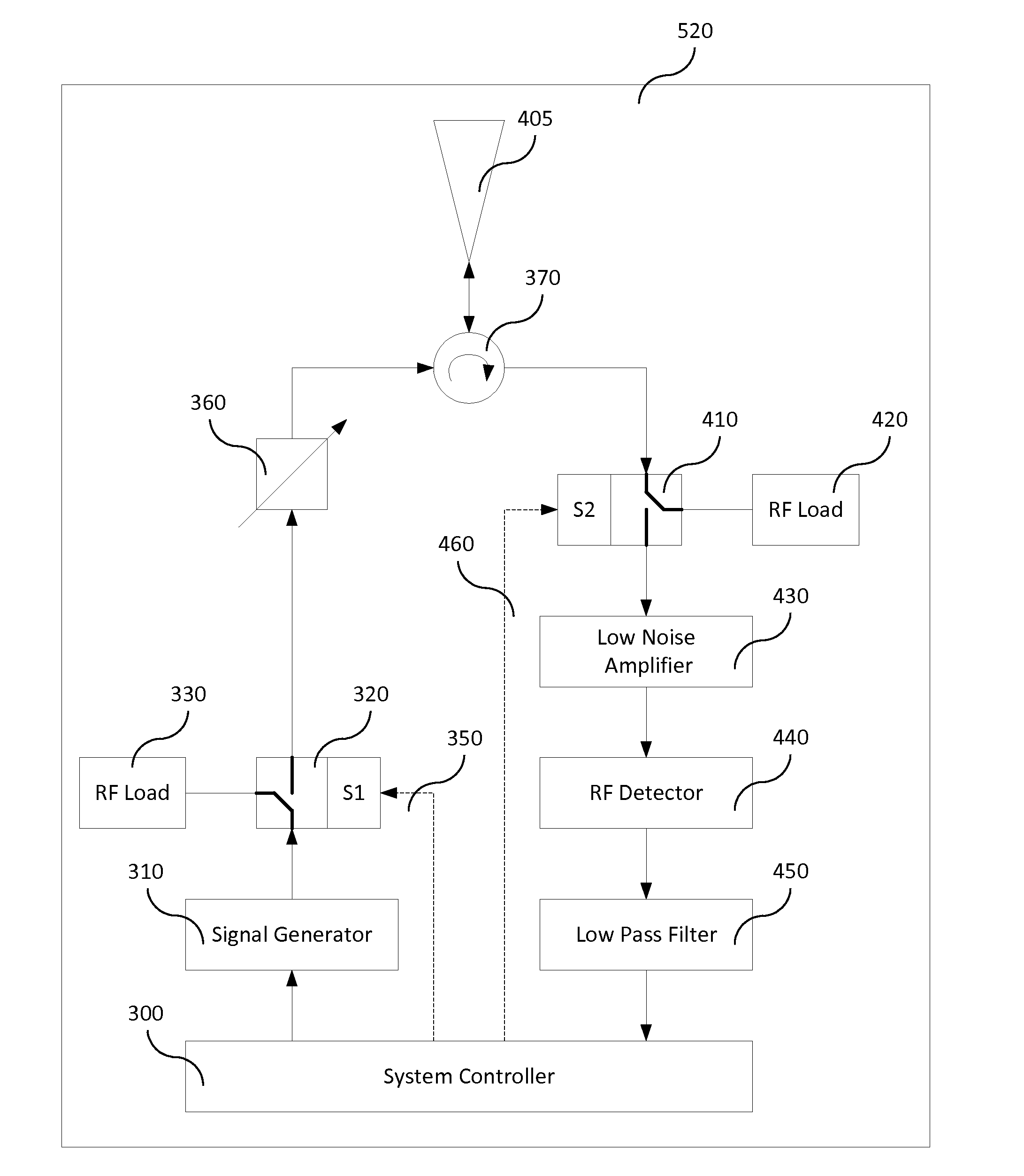
[0025]A typical microwave cavity sensor (MCS) may be similar in construction to a small section of waveguide such as is used in microwave radio communication systems. The MCS may be constructed from a variety of materials such as copper or aluminum and is arranged to have an internal cavity having a consistent cross-section. An external antenna is coupled with the cavity to enable the transfer of electromagnetic energy between the antenna and the cavity. The length of a typical cavity may range from one to ten centimeters and the diameter of the cross-section may be smaller than the length. The cavity may be unpressurised, may be pressurised with a gas such as argon, or may be operated in a vacuum. An MCS may be optimised to measure a particular parameter such as temperature, pressure, stress / strain, moisture, relative movement, the presence of a particular gas, or the like. It will be apparent to those skilled in the art that a wide variety of microwave cavity sensors are possible ...


PUM


Abstract

This invention relates to methods and apparatus for measuring physical properties using microwave cavity sensors. In operation, a number of microwave cavity sensors are interrogated by a remote wireless unit in order to determine the current resonant frequency for the sensor. The current values for various parameters measured by the sensors, such as temperature, stress / stain, or the like, are determined by comparing the current resonant frequency to a first resonant frequency of the sensor, and thus, detect any change in the value of the selected parameter. In particular, the present invention is directed toward extending the range over which such measurements may be performed, using these types of sensors.

Description

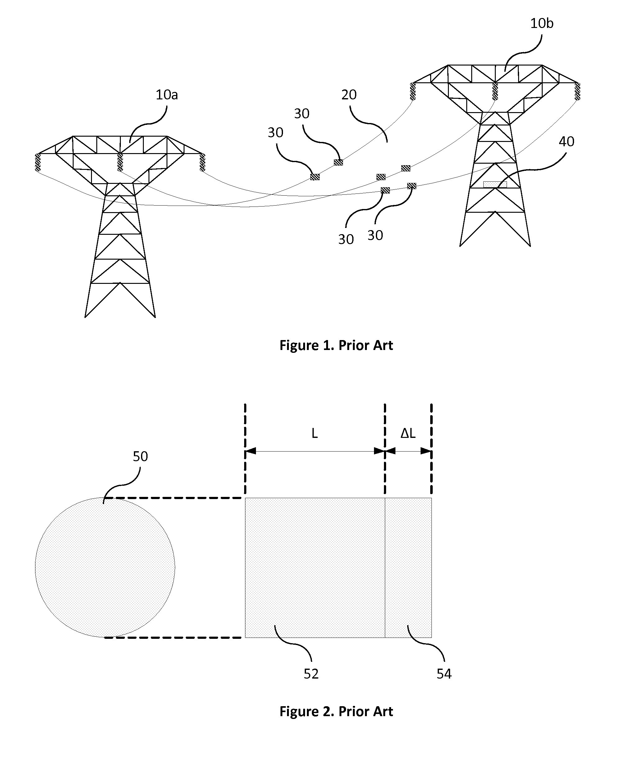
FIELD OF THE INVENTION[0001]This invention relates to methods and apparatus for measuring physical properties. The measurement system comprises a number of microwave cavity sensors connected to one or a plurality of radio antennas, which sensors may be interrogated by a remote wireless unit in order to provide measurement values. In particular, the present invention is directed toward extending the range over which such measurements may be performed.DESCRIPTION OF THE PRIOR ART[0002]There is an increasing requirement to monitor the status and integrity of large structures such as bridges, towers, electricity power lines and similar objects. The structures may be monitored to detect construction defects, to estimate the effects of aging, to provide early warning of deterioration, to optimize their operation in the presence of external effects such as temperature and wind-loading, or measure a variety of other parameters. The use of microwave cavity sensors attached to these structure...

Claims


Application Information

Patent Timeline
IPC IPC(8): G01R27/28
CPCG01K1/026G01K11/006G01L1/25G01L1/26G01M5/0008G01M5/0025G01M5/0041G01M5/0091
Inventor RAMRAJKAR, NAFTALY
Owner SMART AUTONOMOUS SOLUTIONS
Learn More