Method for controlling uplink transmission power and wireless device using same

a wireless device and transmission power technology, applied in the field of wireless communication, can solve the problems of significant interference in the transmission of another ue, difficult for the bs to receive uplink data,

Active Publication Date: 2014-02-20
LG ELECTRONICS INC
View PDF11 Cites 230 Cited by
  • Summary
  • Abstract
  • Description
  • Claims
  • Application Information

AI Technical Summary

Benefits of technology

[0016]When a plurality of timing advance (TA) groups are configured, an uplink transmit power can be adjusted among cells belonging to different TA groups.

Problems solved by technology

It is difficult for the BS to receive uplink data if the transmit power of the UE is too low.
If the transmit power of the UE is too high, uplink transmission may cause a significant interference to transmission of another UE.

Method used


Image

  • Method for controlling uplink transmission power and wireless device using same
  • Method for controlling uplink transmission power and wireless device using same
  • Method for controlling uplink transmission power and wireless device using same

Examples


Embodiment Construction

[0031]A wireless device may be fixed or may have mobility, and may be referred to as another term such as a User Equipment (UE), a mobile station (MS), a user terminal (UT), a subscriber station (SS), or a mobile terminal (MT). In general, the base station may refer to a fixed station communicating with a wireless device, and also may be referred to as another term such as an evolved-NodeB (eNB), a Base Transceiver System (BTS), or an Access Point.

[0032]Hereinafter, it will be described that the present invention is applied based on 3rd Generation Partnership Project (3GPP) long term evolution (LTE) or 3GPP LTE-Advanced (LTE-A). This is for exemplary purposes, and the present invention may be applicable to various wireless communication systems. Hereinafter, LTE includes the LTE and / or the LTE-A.

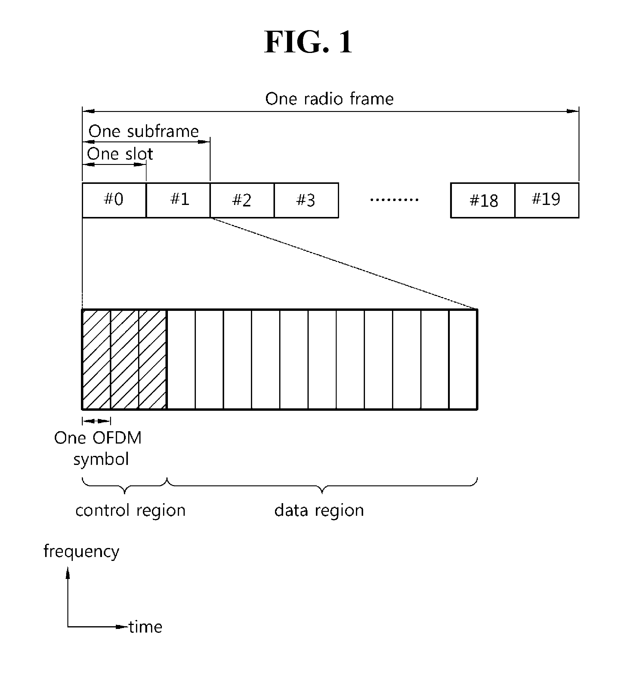
[0033]FIG. 1 illustrates a structure of a downlink radio frame in the 3GPP LTE. This may refer to paragraph 6 of 3GPP TS 36.211 V8.7.0 (2009-05) “Evolved Universal Terrestrial Radio Access (...


PUM


Abstract

Provided are a method for controlling uplink transmission power and a wireless device. The wireless device decides a first transmission power of a first uplink channel, which is transmitted through a first wireless resource from a first serving cell, and decides a second transmission power of a second uplink channel, which is transmitted through a second wireless resource from a second serving cell. The first serving cell belongs to a first timing advance (TA) group, and the second serving cell belongs to a second TA group that differs from the first TA group. All or a portion of the first wireless resource and the second wireless resource overlap, wherein the sum of the first and second transmission powers in the overlapping portion is decided so as not to exceed a maximum transmission power.

Description

CROSS-REFERENCE TO RELATED APPLICATIONS[0001]This application claims the benefit of priority of U.S. Provisional applications No. 61 / 541,044 filed on Sep. 29, 2011, No. 61 / 554,493 filed on Nov. 1, 2011, No. 61 / 591,279 filed on Jan. 27, 2012, No. 61 / 611,590 filed on Mar. 16, 2012, No. 61 / 613,467 filed on Mar. 20, 2012, No. 61 / 644,439 filed on May 9, 2012, No. 61 / 645,566 filed on May 10, 2012, No. 61 / 667,935 filed on Jul. 3, 2012, No. 61 / 678,120 filed on Aug. 1, 2012 and No. 61 / 681,636 filed on Aug. 10, 2012 of which are incorporated by reference in their entirety herein.TECHNICAL FIELD[0002]The present invention relates to wireless communications, and more particularly, to a method for controlling an uplink transmit power in a wireless communication system, and a wireless device using the method.BACKGROUND ART[0003]3rd generation partnership project (3GPP) long term evolution (LTE) is an improved version of a universal mobile telecommunication system (UMTS) and is introduced as the 3...

Claims


Application Information

Patent Timeline
Patent Type & Authority Applications(United States)
IPC IPC(8): H04L5/00H04W4/00
CPCH04L5/0037H04W52/325H04W52/367H04W4/00H04W56/0045H04W56/0005H04W52/146H04L5/0048H04L5/0051H04L27/261H04W72/21H04W74/0833H04L5/0053H04W52/32H04B17/318H04L5/005H04L27/2601H04W52/16H04W72/0446
Inventor AHN, JOON KUIYANG, SUCK CHELYI, YUN JUNGSEO, DONG YOUN
Owner LG ELECTRONICS INC
Why Eureka
Try Eureka