Modular plug

Active Publication Date: 2014-02-20
TYCO ELECTRONICS LOGISTICS AG (CH)
View PDF5 Cites 1 Cited by
  • Summary
  • Abstract
  • Description
  • Claims
  • Application Information

AI Technical Summary

Benefits of technology

The patent is about a modular plug that has a stuffer cap with a cable channel and a strain relief member. The strain relief member has a base and a spring beam that presses wires of the cable into electrical contact with the plug contacts. The strain relief member has a slot that allows the spring beam to pinch the cable between the interior side of the stuffer cap and the spring beam. The technical effect of this invention is to provide a reliable and efficient connection between cables and plug contacts with improved insulation and durability.

Problems solved by technology

Such connectors have limited current carrying capability.

Method used


Image

  • Modular plug
  • Modular plug
  • Modular plug

Examples


Embodiment Construction

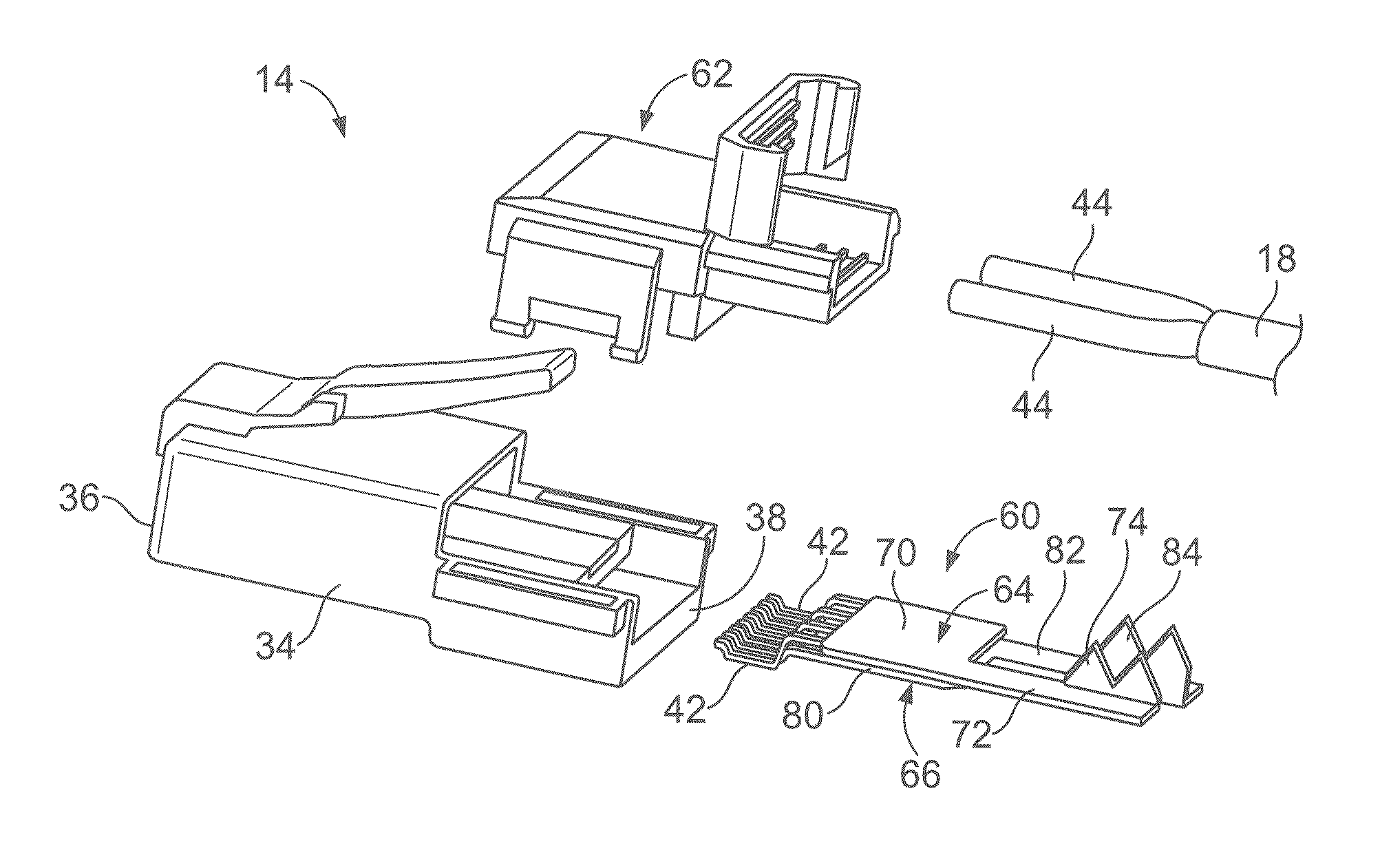
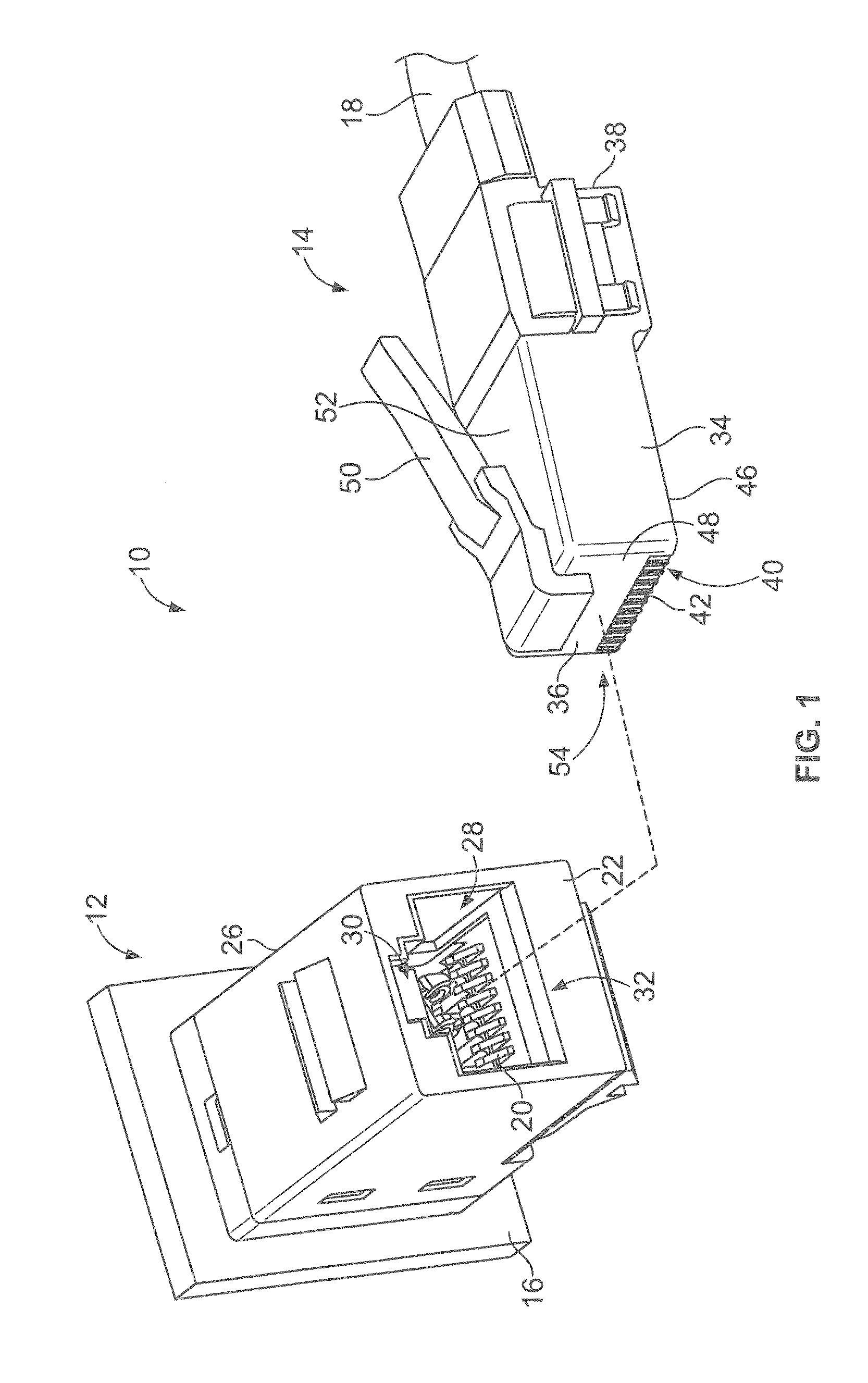
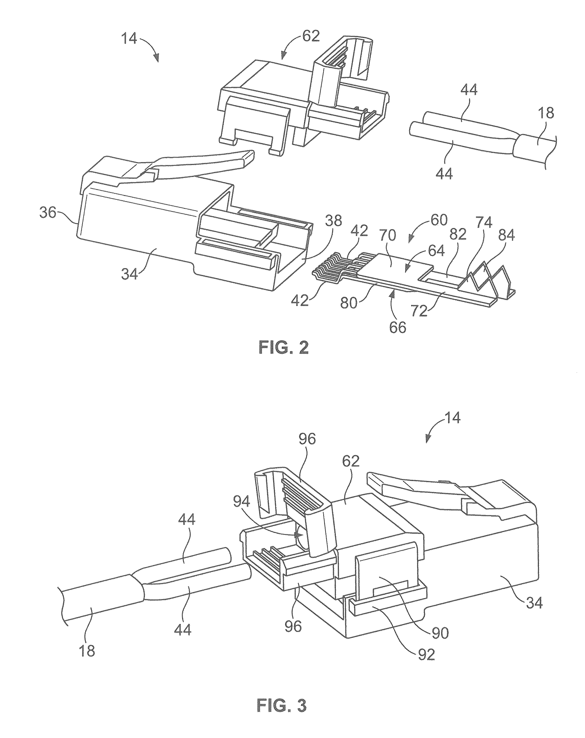
[0020]FIG. 1 is a perspective view of an electrical connector system 10 formed in accordance with an exemplary embodiment. The electrical connector system 10 includes a modular jack 12 and a modular plug 14 configured to be mated with the jack 12. The jack 12 and plug 14 may be referred to hereinafter as electrical connector(s). In an exemplary embodiment, the jack 12 is provided on a substrate, such as a printed circuit board 16. The jack 12 may be mounted vertically on the printed circuit board 16, horizontally on the printed circuit board 16 or at other configurations. Optionally, the jack may be a right angle jack with the printed circuit board 16 perpendicular to the mating end. The jack 12 may be mounted on a wall or panel, or, alternatively, may be mounted in an electrical device or apparatus. Alternatively, the jack 12 may be wire or cable mounted at an end of a power cable. In an exemplary embodiment, the plug 14 is provided at an end of a power cable 18 that transmits powe...


PUM


Abstract

A modular plug includes a plug housing, plug contacts held by the plug housing, and a stuffer cap coupled to the plug housing. The stuffer cap includes a cable channel configured to receive a cable therein. The stuffer cap includes an interior side that defines at least a portion of the cable channel. The modular plug includes a strain relief member held by the plug housing. The strain relief member includes a base and a spring beam extending from the base such that the spring beam is cantilevered from the base. The spring beam is configured to engage the cable and thereby pinch the cable between the interior side of the stuffer cap and the spring beam.

Description

CROSS REFERENCE TO RELATED APPLICATIONS[0001]This application is a continuation-in-part of U.S. patent application Ser. No. 13 / 586,408, filed Aug. 15, 2012, and entitled “MODULAR PLUG FOR POWER APPLICATIONS”, the subject matter of which is herein incorporated by reference in its entirety.BACKGROUND OF THE INVENTION[0002]The subject matter herein relates generally to modular plugs.[0003]In electrical systems, there is increasing concern for powering electronic devices. Some electrical systems supply power over typical connectors. For example, industry standard type RJ-45 communication connectors provide Power over Ethernet connections by supplying current along the 8 signal circuits. Such connectors have limited current carrying capability.[0004]A connector capable of having higher current carrying ability is needed.BRIEF DESCRIPTION OF THE INVENTION[0005]In one embodiment, a modular plug includes a plug housing, plug contacts held by the plug housing, and a stuffer cap coupled to th...

Claims


Application Information

Patent Timeline
IPC IPC(8): H01R13/514
CPCH01R13/514H01R4/2433H01R13/506H01R13/5825H01R13/5837H01R24/64H01R2201/04H01R24/58
Inventor DAILY, JR., CHRISTOPHER GEORGEHOWARD, EDWARD JOHN
Owner TYCO ELECTRONICS LOGISTICS AG (CH)
Why Eureka
Try Eureka