Fiber-Bragg-grating-based strain measuring apparatus, system and method

a strain measurement and fiberbragging technology, applied in the field of fiberbragging-based strain measurement apparatus, system and method, can solve the problems of irreparable damage to the fiber, no method or technique for accurately measuring this stress, and environmental degradation

Inactive Publication Date: 2002-01-08
CIENA
View PDF2 Cites 86 Cited by
  • Summary
  • Abstract
  • Description
  • Claims
  • Application Information

AI Technical Summary

Problems solved by technology

Such environmental degradation is a widely-studied problem and includes water molecules attacking the chemical bonds in the optical fiber.
As is also known in the art, bending optical fiber affects the useful life of the fiber and exceeding a minimum bend radius can irreparably damage the fiber.
To date, no method or technique exists for accurately measuring this stress and comparing the stress applied to the fiber inside the splice protector to the stress outside the splice protector.

Method used


Image

  • Fiber-Bragg-grating-based strain measuring apparatus, system and method
  • Fiber-Bragg-grating-based strain measuring apparatus, system and method

Examples


Embodiment Construction

The following detailed description of the invention refers to the accompanying drawings. The same reference numbers in different drawings identify the same or similar elements. Also, the following detailed description does not limit the invention. Instead, the scope of the invention is defined by the appended claims and equivalents thereof.

The expression "optically communicates" as used herein refers to any connection, coupling, link or the like by which optical signals carried by one optical system element are imparted to the "communicating" element. Such "optically communicating" devices are not necessarily directly connected to one another and may be separated by intermediate optical components or devices. Likewise, the expressions "connection" and "operative connection" as used herein are relative terms and do not necessarily require a direct physical connection.

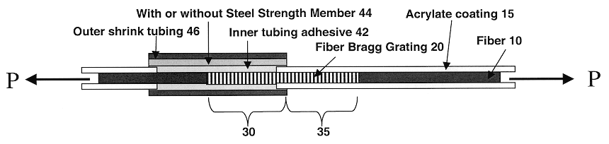
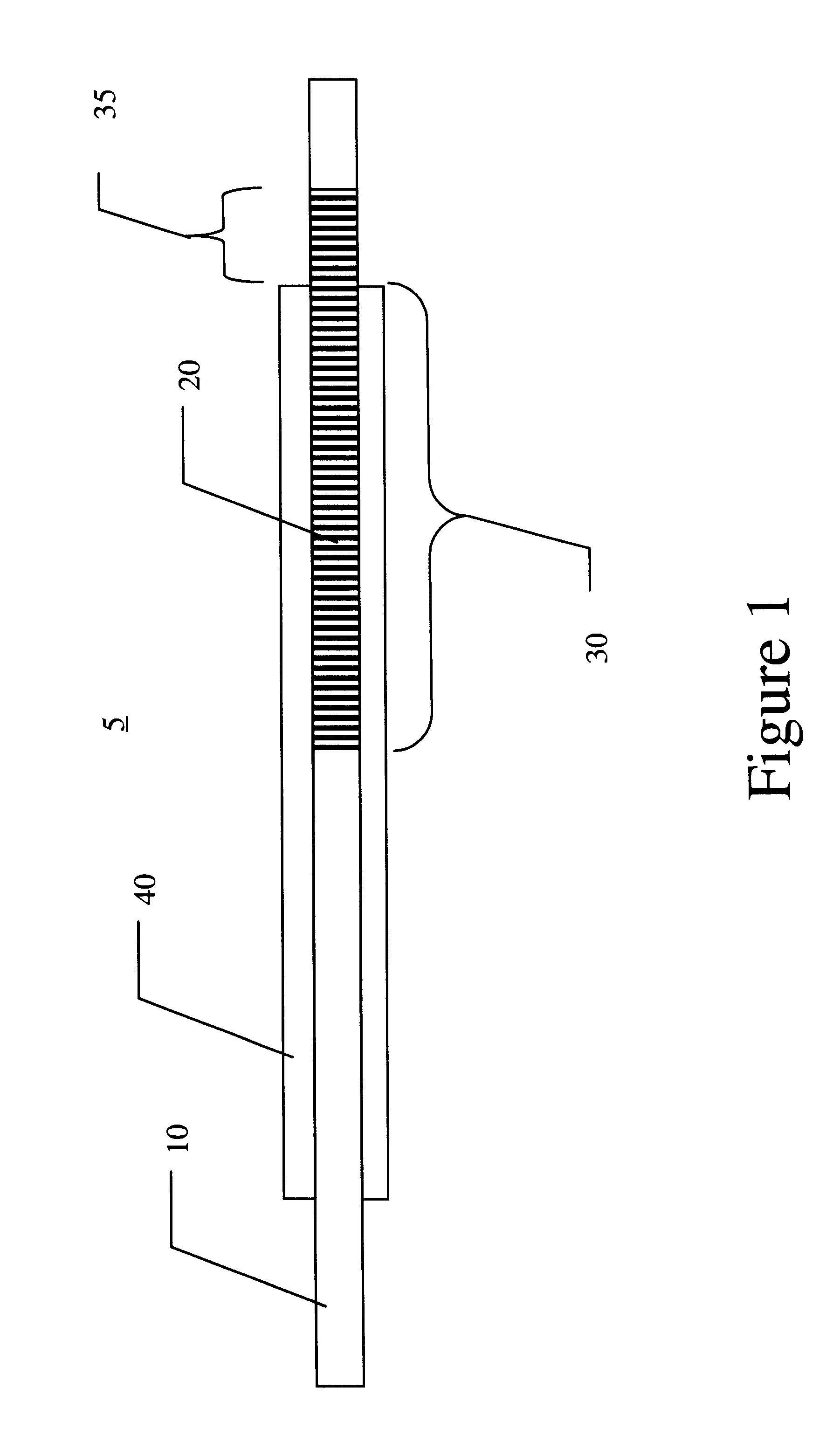
The invention was originally developed to determine the strain-relief capability of a splice protector as well as the ...


PUM


Abstract

The invention was originally developed to determine the strain-relief capability of a fusion splice protector as well as the compressive stress imparted to a fusion splice by the splice protector. The invention also permits performance and comparative analyses of splice protectors as well as any package in which the optical fiber is at least partially disposed. To those ends a fiber Bragg grating (FBG) is axially arranged relative to the package such that a free or reference section of the FBG protrudes from the package while a shielded section lies within the package. Broadband light is supplied to the FBG which reflects certain wavelengths that are measured by an optical spectrum analyzer. The FBG reflected spectra will be split into two peaks as the reference and shielded sections experience different amounts or types of stress thereby providing a powerful analysis tool. A wavelength shift in the reflected spectra reveals the amount of stress experienced by the reference and free sections and permits a qualitative and quantitative analysis of the stress applied by the package and the package's ability to protect fiber from stress (e.g. such as that imposed by a tension pull test). Measurements may be made after a variety of conditions are changed such as splice protector curing, axial tension application, axial tension release, time, and age accelerating environments. Comparative studies and various other calculations may also be performed to evaluate different packages.

Description

1. Field of InventionThe invention generally relates to an apparatus, system and method for measuring tensile and / or compressive stresses experienced by an optical fiber.2. Description of Related ArtUsing an in-fiber Bragg grating to measure temperature and strain is a conventional and widely used technique. Such techniques take advantage of periodicity changes in the grating that are caused by temperature and / or strain changes. For example, an increased temperature or axial tension expands the period between grating etchings and causes a corresponding change in the wavelength(s) reflected by the grating.A recent example of such a system is described in Ecke et al. (U.S. Pat. No. 6,137,565) which uses a plurality of fiber Bragg gratings to accurately determine the absolute physical state (temperature or stain) in an optical fiber.As is known in the art, sections of optical fiber may be spliced together using an electric arc or other energy source that fuses the respective fiber ends...

Claims


Application Information

Patent Timeline
Patent Type & Authority Patents(United States)
IPC IPC(8): G01D5/353G01D5/26
CPCG01D5/35316G01L1/246
Inventor CHANG, CHIA-CHENSAHINCI, ERINMAHMOOD, WAQAR
Owner CIENA
Why Eureka
Try Eureka