Connector

a technology of connecting rods and connectors, applied in the direction of coupling device connection, coupling protective earth/shielding arrangement, securing/insulating coupling contact members, etc., can solve the problems of disadvantageous miniaturization of connectors, and achieve the effect of facilitating vibration and facilitating vibration

Inactive Publication Date: 2014-02-20
SUMITOMO WIRING SYST LTD
View PDF5 Cites 29 Cited by
  • Summary
  • Abstract
  • Description
  • Claims
  • Application Information

AI Technical Summary

Benefits of technology

[0008]The bent intermediate portion is formed by bending a conductive plate material substantially at a right angle. Formation of the intermediate portion of the inner conductive member of the metal plate material permits a small bending radius and enables the connector to be miniaturized.
[0011]The intermediate portion may be fastened to the housing by a screw. According to this configuration, the intermediate portion is arranged at the side of the outer wire crimping portion susceptible to vibration. Thus, the impact of vibration is blocked easily. Further, a fastening direction by the screw is perpendicular to a vibration transmission direction and the impact of vibration is blocked more easily.
[0012]The intermediate portion may be press-fitted into the housing. Thus, the intermediate portion can be fixed to the housing by an easy press-fit method. Furthermore, it is not necessary to provide a terminal block with a nut press-fit into the housing and the housing can be miniaturized.

Problems solved by technology

However, vibration from the body is transmitted to a terminal fitting via the conductive member, and may cause trouble where the terminal fitting is connected to a mating terminal fitting.
However, a large diameter wire requires a large bending radius to bend the wire at a right angle in a corner of the connector main body and to fix the wire to the connector main body.
This is disadvantageous in miniaturizing the connector.

Method used


Image

  • Connector
  • Connector
  • Connector

Examples


first embodiment

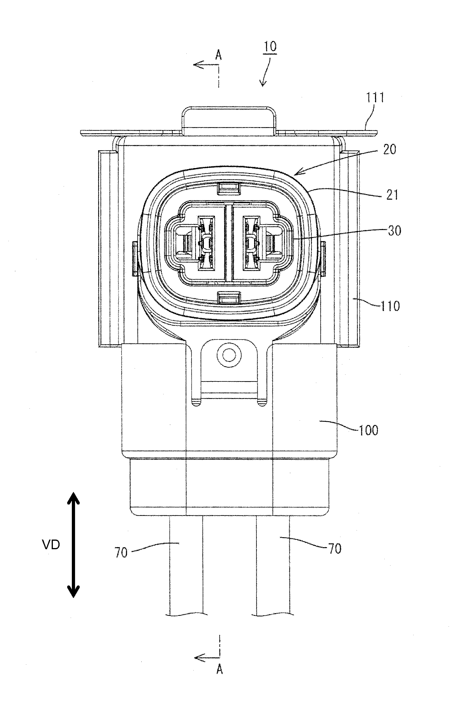
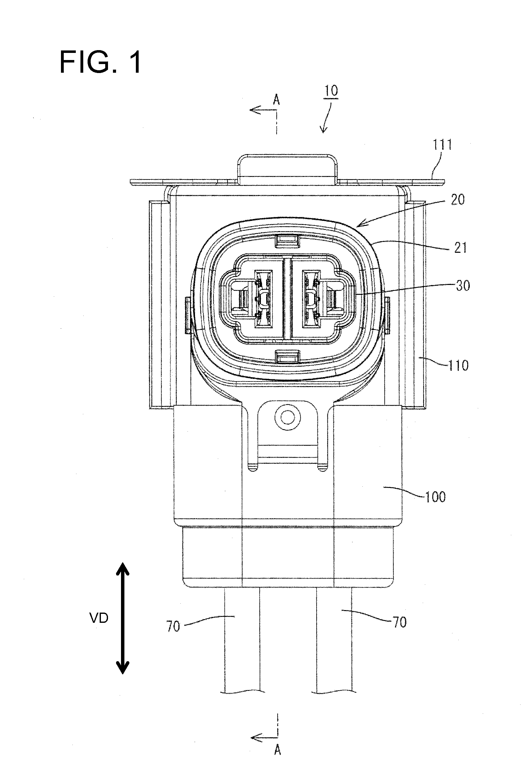
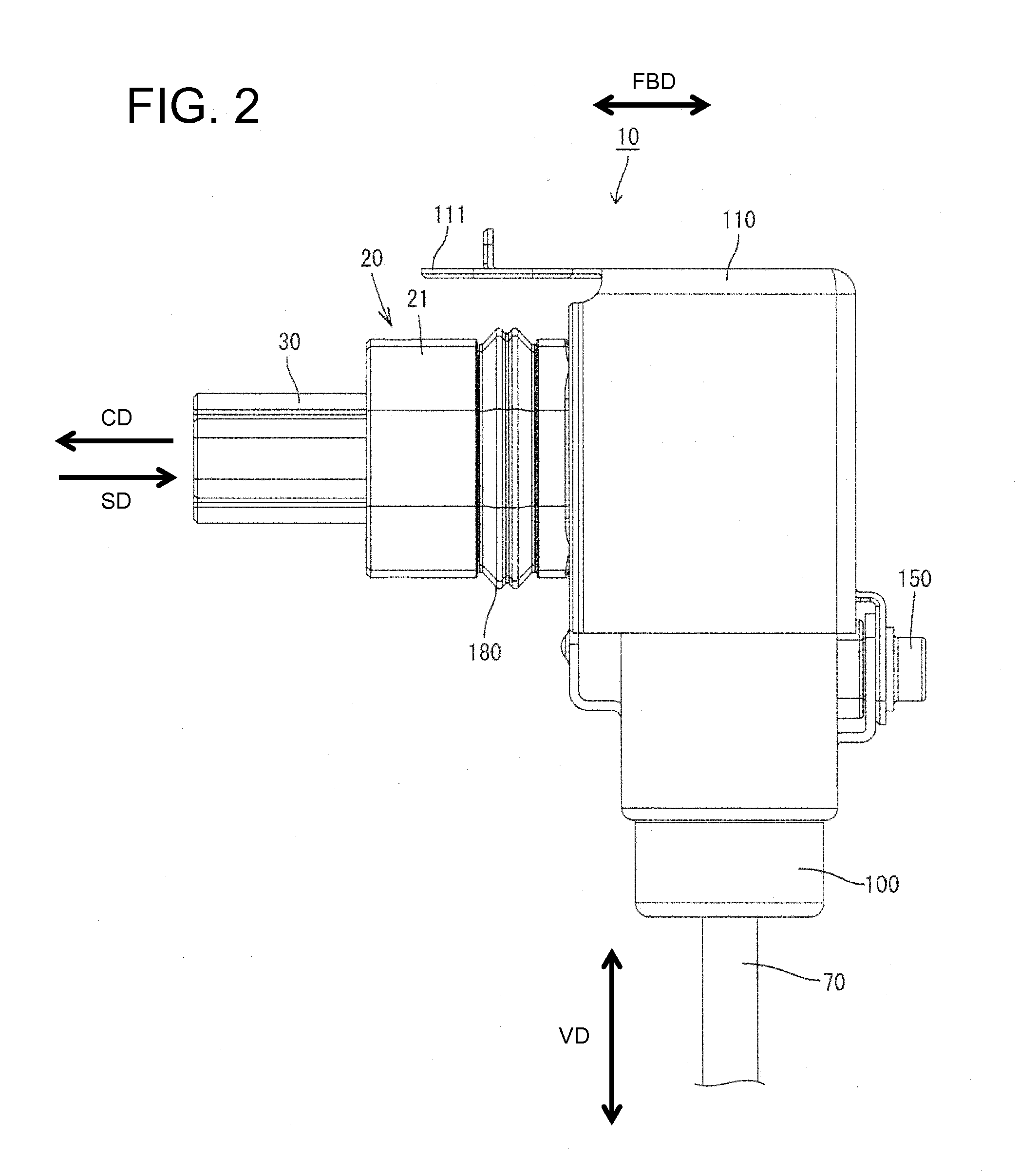
[0032]the invention is described with reference to FIGS. 1 to 4. A connector 10 of this embodiment is to be mounted on a shield case (not shown) of a device (e.g. inverter, motor or the like of a vehicle such as a hybrid vehicle or an electric vehicle). A device-side connector is arranged at a position substantially facing the connector 10 in a connecting direction in the shield case is connectable to the connector 10. Note that a vertical direction VD is based on that of FIG. 1 in the following description. Further, forward and backward directions FBD are based on lateral directions of FIG. 2. A leftward direction (connecting direction CD to the device-side connector) is referred to as a forward direction and a rightward direction (separating direction SD from the device-side connector) is referred to as a backward direction.

[0033]As shown in FIG. 4, the connector 10 includes a housing 20, inner conductive members 50, a cover 60, outer wires 70, resilient or rubber plugs 80, a plug...


PUM


Abstract

A connector (10) includes a housing (20) connectable to a mating housing of the mating connector. A female terminal (52) is held in the housing (20) and includes a terminal connecting portion (52A) to be connected to a mating terminal provided in the mating connector and a barrel (52B) connected to the terminal connecting portion (52A). A flexible outer wire (70) is pulled out to outside from the interior of the housing (20). An inner conductive member (50) connects the barrel (52B) and the outer wire (70) in the housing (20) and includes an intermediate portion (53C) formed by bending a metal plate material substantially at a right angle. The intermediate portion (53C) is fixed to the housing (20).

Description

BACKGROUND[0001]1. Field of the Invention[0002]The invention relates to a connector.[0003]2. Description of the Related Art[0004]Japanese Unexamined Patent Publication No. 2000-277217discloses a connector that prevents trouble during a connection due to a dimensional accuracy error or the like. More particularly, a leaf spring of a spring washer is arranged between a connector main body and a bottom plate and is deflected when a mating connector is inserted. Thus, the connector main body pivots according to the position of the mating connector.[0005]A conductive member is pulled out from the connector main body of Japanese Unexamined Patent Publication No. 2000-277217 to a body side and is connected to the body. However, vibration from the body is transmitted to a terminal fitting via the conductive member, and may cause trouble where the terminal fitting is connected to a mating terminal fitting. A flexible wire can be used as the conductive member and can be fixed to the connector...

Claims


Application Information

Patent Timeline
Patent Type & Authority Applications(United States)
IPC IPC(8): H01R13/533
CPCH01R13/533H01R13/447H01R13/5202H01R13/5219H01R13/6315H01R13/6581H01R24/20H01R2103/00H01R13/40
Inventor ITSUKI, KIYOTAKAMATSUOKA, HIROYUKIMIYAZAKI, SHOKASHIWADA, TOMOKAZU
Owner SUMITOMO WIRING SYST LTD
Why Eureka
Try Eureka