
Device and Method for Generating Light of a Predetermined Spectrum with at Least Four Differently Colored Light Sources

a technology of predetermined spectrum and light source, applied in the direction of light source, lighting apparatus, electrical apparatus, etc., can solve the problems of increased cost of leds, increased production costs, and increased production costs of leds, and achieve the effect of simple design

Active Publication Date: 2014-02-27
AIRBUS DEFENCE & SPACE
View PDF2 Cites 22 Cited by
  • Summary
  • Abstract
  • Description
  • Claims
  • Application Information

AI Technical Summary

Benefits of technology

The present patent application is about a lighting unit that uses an optimization algorithm to adjust the settings of its light sources based on various criteria such as color rendering index, power demand, and sensor feedback. This allows for a consistent and uniform lighting quality throughout the entire operation period of the lighting unit. The lighting unit can use a cost-effective sensor and can adapt to changes in color and brightness over time. Additionally, the lighting unit can be optimized in the CIE-standardized X, Y, Z color space, providing better color detection and accuracy. The technical effects of this patent application include improved lighting quality, cost-effectiveness, and improved color detection and accuracy.

Problems solved by technology

In semiconductor based lighting elements, such as LEDs, the color spectrum and the brightness (intensity) change with increasing operation duration, which can be perceived as interference unless compensation is provided for this interference.
In addition, LEDs are also affected by a dispersion of their technical properties with regard to brightness and color during manufacture.
The narrower the dispersion selection, the more expensive are the LEDs.
However, the disadvantage here is that, on the one hand, the sensor has to be adjusted to the frequency spectra of the LEDs for the control unit to function sufficiently.
Furthermore, with this system, a lighting device with more than 3 light sources having different color spectra—for example, a yellow or white LED as fourth LED—can no longer be controlled, because the result of this control is no longer unequivocal, since several luminosity settings of the four light sources can generate the same color impression in the XYZ color space.
This has the disadvantage that only one individual light source can always be observed by the measuring method used.
It is also disadvantageous that the described adjustment of the color and brightness values of the light function only in one operating state in which the individual light sources are adjusted individually.

Method used


Image

  • Device and Method for Generating Light of a Predetermined Spectrum with at Least Four Differently Colored Light Sources
  • Device and Method for Generating Light of a Predetermined Spectrum with at Least Four Differently Colored Light Sources
  • Device and Method for Generating Light of a Predetermined Spectrum with at Least Four Differently Colored Light Sources

Examples


Embodiment Construction

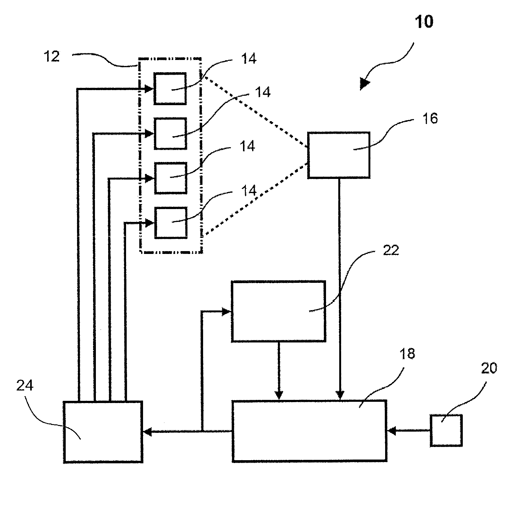
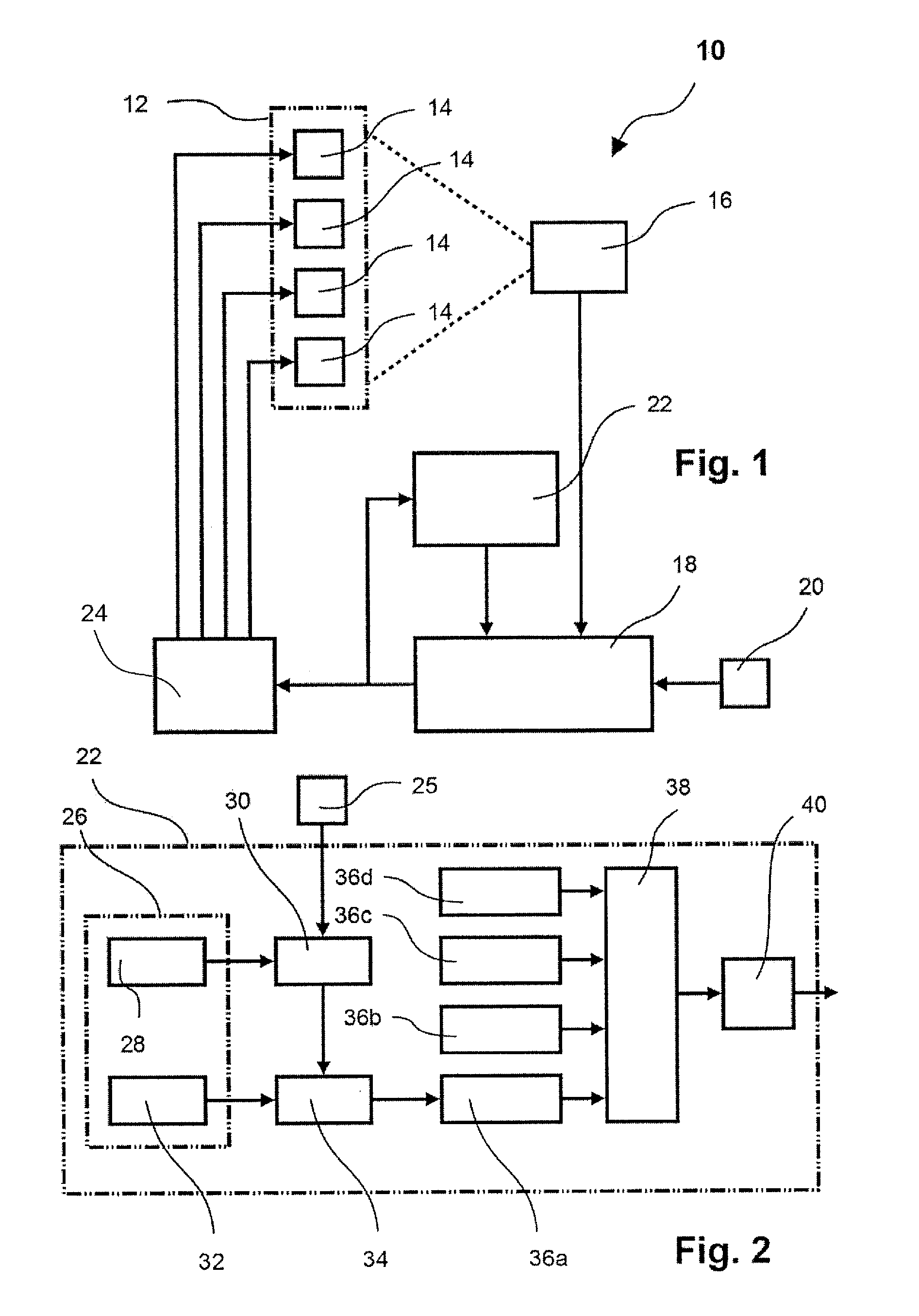
[0033]The device 10 according to the present application comprises, according to FIG. 1, a lighting unit 12 which comprises four or more light sources 14 which have different color spectra. For example, a red LED (620 nm), a green LED (520 nm), a blue LED (460 nm), and a yellow LED (590 nm) can be provided. Furthermore, to increase the luminosity, several light sources of the same color spectrum can be provided, which are preferably energized jointly (in parallel or in series), but which are considered to be a light source or LED in the context of this embodiment. These light sources emit substantially in the same direction which is not further designated here. It is essential that, in the radiation field of all the light sources, a sensor 16 is arranged, which is preferably designed as an RGB or XYZ sensor, and which transfers corresponding data of the received radiation spectrum to an optimization unit 18. The optimization unit 18 furthermore contains, as input signal, a radiation...


PUM


Abstract

A lighting device and method with a lighting unit which includes several light sources having different color spectra, with a sensor for determining the spectral power distribution emitted by the lighting unit, with a control unit which, as a function of a predetermined spectral power distribution as well as of the spectral power distribution measured by the sensor, acts on a drive unit which individually energizes the light sources of the lighting unit, so that the emitted light has predetermined spectral power distribution, wherein the lighting unit includes at least four light sources, and the control unit uses an optimization algorithm which, as an optimization goal, maximizes a coefficient of weighted sensor values, the coefficient being calculable from individual drive data of the light sources. A secondary condition is met when error between the predetermined spectral power distribution and the measured spectral power distribution is smaller than a limit value.

Description

CROSS-REFERENCE TO RELATED APPLICATIONS[0001]The present application claims priority to German Patent Application Ser. No. 10 2012 107 706.1 filed on 22 Aug. 2012, the contents of which are incorporated herein by reference in their entirety.BACKGROUND[0002]1. Field of Technology[0003]The present application relates to a lighting device with a lighting unit including several light sources having different color spectra, with a sensor for determining the spectral power distribution (SPD) emitted by the lighting unit, with a control unit which, as a function of a predetermined spectral power distribution as well as of the spectral power distribution measured by the sensor, acts upon a drive unit which individually energizes the light sources of the lighting unit, so that the emitted light has the predetermined spectral power distribution. In this context, color spectrum denotes the electromagnetic waves of a range of defined bandwidth and intensity in the color space visually perceivab...

Claims


Application Information

Patent Timeline
IPC IPC(8): H05B33/08H05B44/00
CPCH05B33/0869H05B33/08H05B45/22H05B45/10H05B47/105H05B45/24
Inventor CAPPITELLI, MARIOKLOSTERMANN, SONKEVOGT, DIETMAROLBERT, MICHAEL
Owner AIRBUS DEFENCE & SPACE
Learn More