
Image display device capable of displaying image in a desired orientation, method of controlling the same, and storage medium

Inactive Publication Date: 2014-02-27
CANON KK
View PDF6 Cites 7 Cited by
  • Summary
  • Abstract
  • Description
  • Claims
  • Application Information

AI Technical Summary

Benefits of technology

The invention provides an image display device that can save time and effort by automatically rotating images based on their orientation and the device's attitude. This allows users to easily view image data in a desired orientation without needing to manually adjust it. The device also detects and restricts unintended rotation of images, ensuring that the user has control over the image's display direction. This improves the user experience and makes the device more convenient and intuitive.

Problems solved by technology

In Japanese Patent Laid-Open Publication No. 2000-312329, described above, when the user is about to view image data, to which image rotation information unintended by a user is added, in a desired orientation, the user is required to perform various operations, which costs the user much time and labor.

Method used


Image

  • Image display device capable of displaying image in a desired orientation, method of controlling the same, and storage medium
  • Image display device capable of displaying image in a desired orientation, method of controlling the same, and storage medium
  • Image display device capable of displaying image in a desired orientation, method of controlling the same, and storage medium

Examples


first embodiment

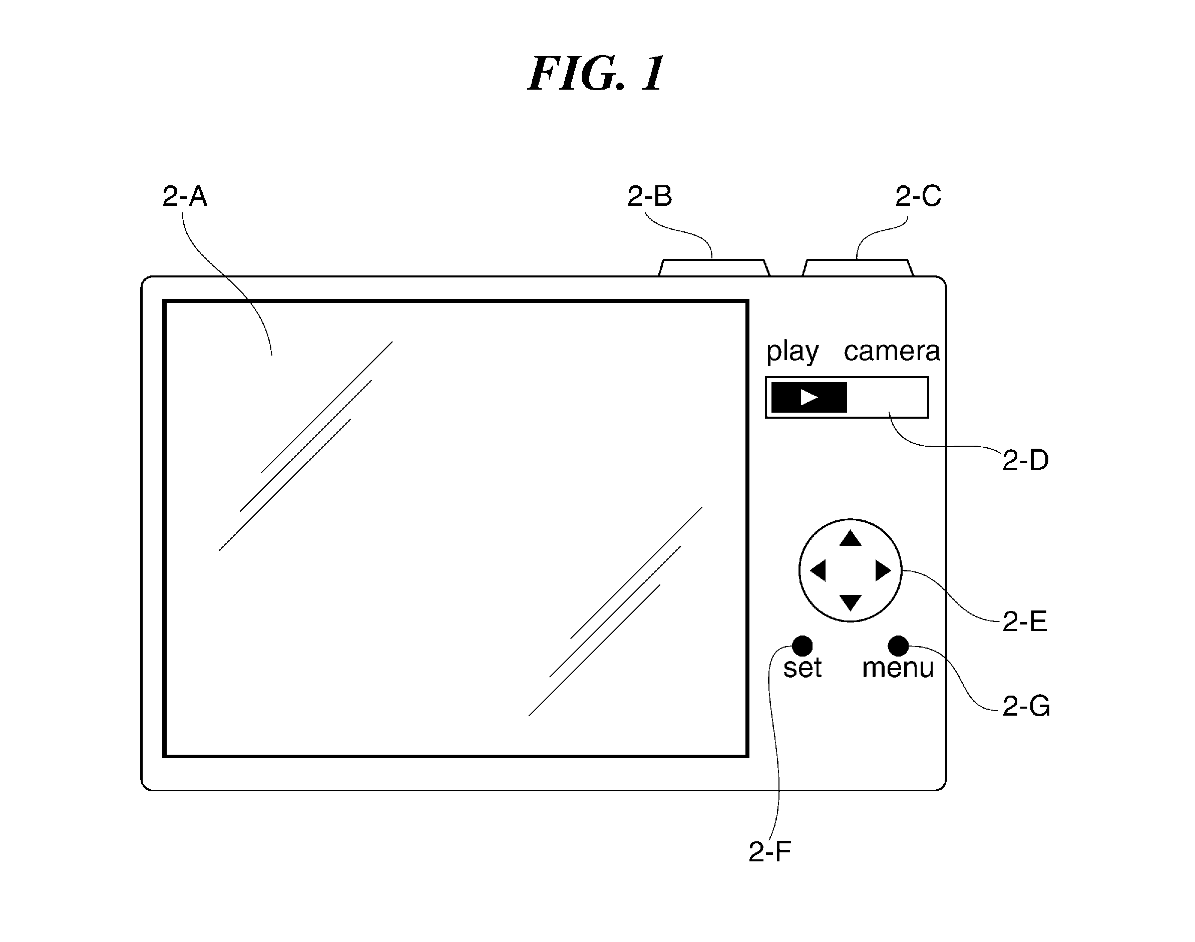
[0024]FIG. 1 is a diagram of an image pickup apparatus including an image display device according to the present invention, as viewed from the rear thereof.

[0025]The image pickup apparatus shown in FIG. 1 is e.g. a digital camera (hereinafter simply referred to as the “camera”), which is capable of recording and playing back image data obtained through photographing an object. The camera includes a photographing mode and a playback mode.

[0026]Note that although it is assumed here that image data is recorded by the camera e.g. in a image file with an aspect ratio of 4:3 in the JPEG format, image data may be recorded in an uncompressed format or the like. Further, the aspect ratio of the image file is not limited to 4:3.

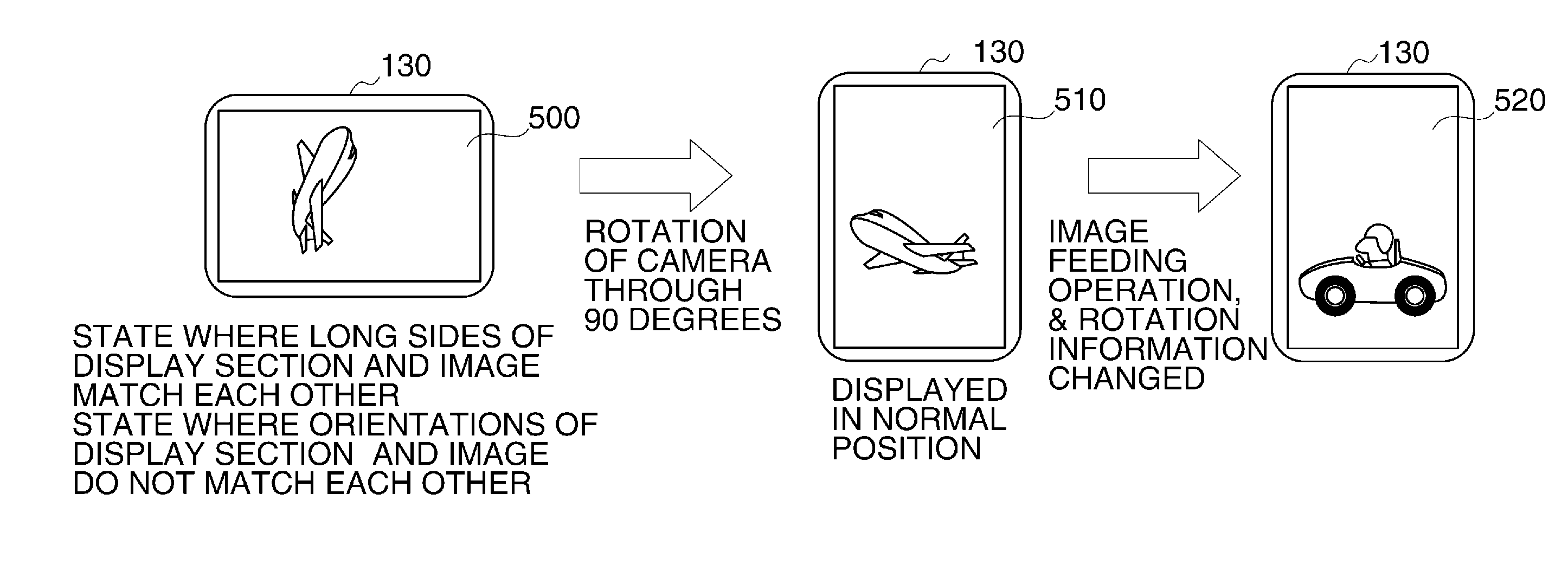
[0027]A liquid crystal display (LCD) 2-A, which is a display section, is disposed on the rear surface of a camera housing, and an image (photographed image) to be checked by a user before photographing is displayed on the LCD 2-A.

[0028]Further, when image data recorde...

second embodiment

[0108]Next, an image display device according to the present invention will be described.

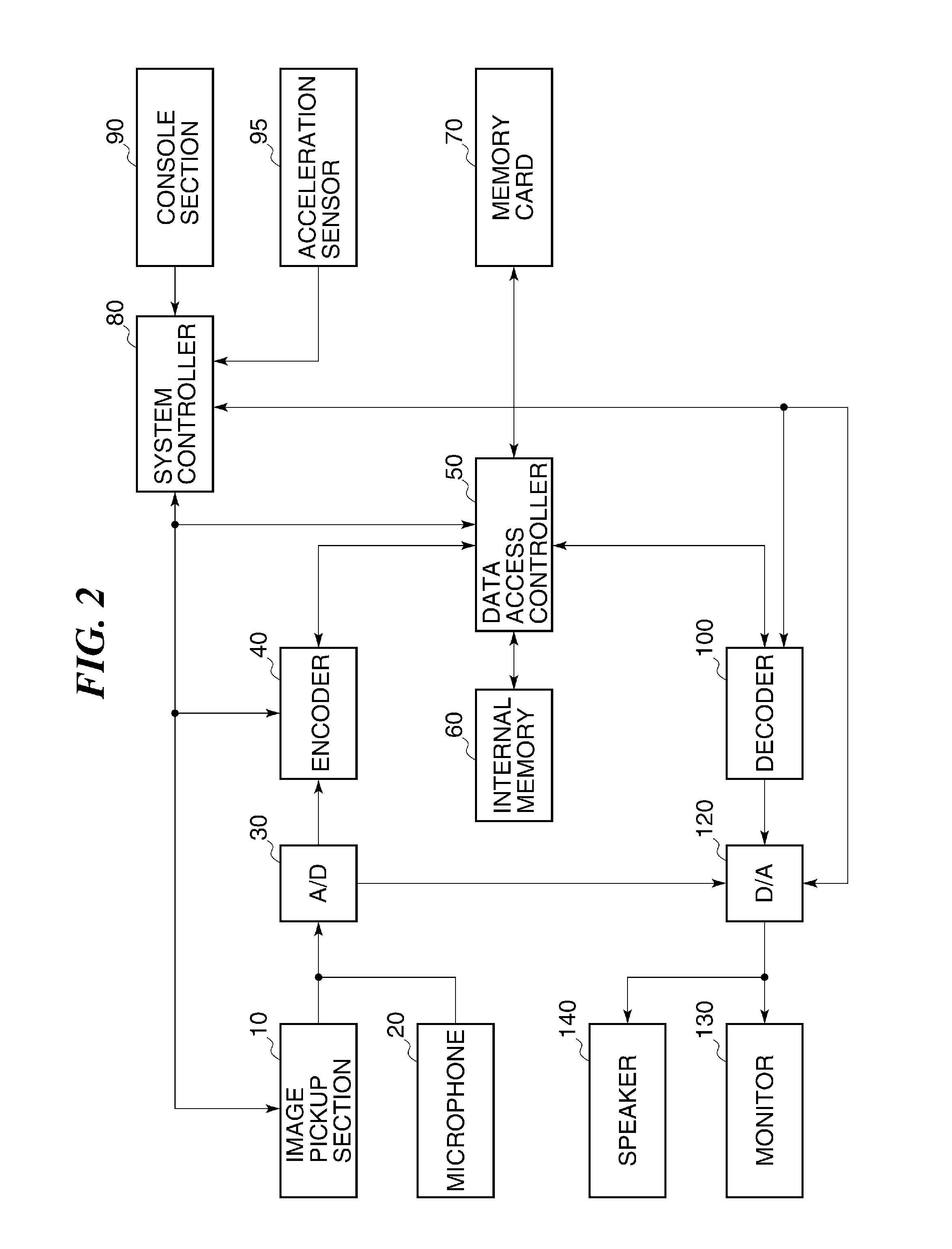
[0109]The following description will be given of a camera as an image pickup apparatus including the image display device according to the second embodiment, by way of example. Further, in the second embodiment, the camera has the same hardware configuration as that of the camera shown in FIGS. 1 and 2.

[0110]FIG. 6 is a flowchart of an image playback process executed by the camera including the image display device according to the second embodiment of the present invention when in the playback mode. The same steps in FIG. 6 as those in the FIG. 3 flowchart are denoted by the same step numbers, and description thereof is omitted.

[0111]As described with reference to FIG. 3, the system controller 80 sets the “long-side match flag and the rotation control flag to off in the step 310. Then, the system controller 80 proceeds to a step S620 to execute the image rotation process.

[0112]FIG. 7 is a flowc...

third embodiment

[0142]Next, an image display device according to the present invention will be described.

[0143]The following description will be given of a camera as an image pickup apparatus including the image display device according to the third embodiment, by way of example. Further, in the third embodiment, the camera has the same hardware configuration as that of the camera shown in FIGS. 1 and 2.

[0144]Although in the third embodiment, an image playback process is executed according to the flowchart described with reference to FIG. 3, an image rotation process is different from the image rotation process described with reference to FIG. 4.

[0145]FIG. 9 is a flowchart of the image rotation process executed by the camera including the image display device according to the third embodiment. The same steps in FIG. 9 as those in FIG. 4 flowchart are denoted by the same step numbers, and description thereof is omitted.

[0146]As described hereinabove with reference to FIG. 4, in the step S530, the sy...


PUM


Abstract

An image display device capable of saving time and effort required for viewing image data, to which image rotation information unintended by a user is added, in a desired orientation. An acceleration sensor detects an attitude of the image display device. A system controller controls the direction of display of an image based on the image rotation information and the detected attitude of the image display device. When the image display device is rotated from a state where the long side of the image displayed on a monitor and that of the monitor do not match each other, the system controller rotates the image such that the long sides of the image and the monitor match each other, and then, the system controller restricts rotation of the displayed image.

Description

BACKGROUND OF THE INVENTION[0001]1. Field of the Invention[0002]The present invention relates to an image display device, a method of controlling the same, and a storage medium, and more particularly to a technique for displaying an image in a desired orientation by rotating the image.[0003]2. Description of the Related Art[0004]In general, when a digital image obtained by an image pickup apparatus, such as a digital camera, is recorded, information indicative of an orientation of the digital image displayed on a screen (image rotation information), in units of 90 degrees, is added to the digital image, according to an attitude of the image pickup apparatus at the time of photographing.[0005]For example, in Japanese Patent Laid-Open Publication No. 2000-312329, when a digital image (image data) having image rotation information added thereto is displayed, the digital image is rotated, by taking an attitude of a display section into account, in units of 90 degrees, for display accord...

Claims


Application Information

Patent Timeline
IPC IPC(8): G06T3/60
CPCG06T3/60G06F1/1626H04N23/667H04N23/63
Inventor MIKAWA, TAKUMA
Owner CANON KK
Features
  • Generate Ideas
  • Intellectual Property
  • Life Sciences
  • Materials
  • Tech Scout
  • Unparalleled Data Quality
  • Higher Quality Content
  • 60% Fewer Hallucinations
Learn More