
Engine and engine-driven working machine

Inactive Publication Date: 2014-03-06
HITACHI KOKI CO LTD
View PDF20 Cites 8 Cited by
  • Summary
  • Abstract
  • Description
  • Claims
  • Application Information

AI Technical Summary

Benefits of technology

The present invention aims to prevent the engine from running out unburned air-fuel mixture and control the number of times it combusts, ensuring optimal performance during idling and working. This is achieved by forming multiple systems of scavenging passages with different opening / closing systems. This reduces the likelihood of combustion byproducts escaping without being fully combusted and ensures efficient output and acceleration during use.

Problems solved by technology

Regarding the two methods of Patent Documents 1 and 2, the former one has a problem that the scavenging volume cannot be optionally selected depending on the revolution speed of the engine, and the latter one has a defect that the mechanism thereof is large and complex.
In addition to that, in the technique of Patent Document 2, in an idling state, an engine performs intermittent combustion; therefore, there are problems that the blow-though volume of the uncombusted air-fuel mixture is particularly large and that operation is not stable with large vibrations.

Method used


Image

  • Engine and engine-driven working machine
  • Engine and engine-driven working machine
  • Engine and engine-driven working machine

Examples


first embodiment

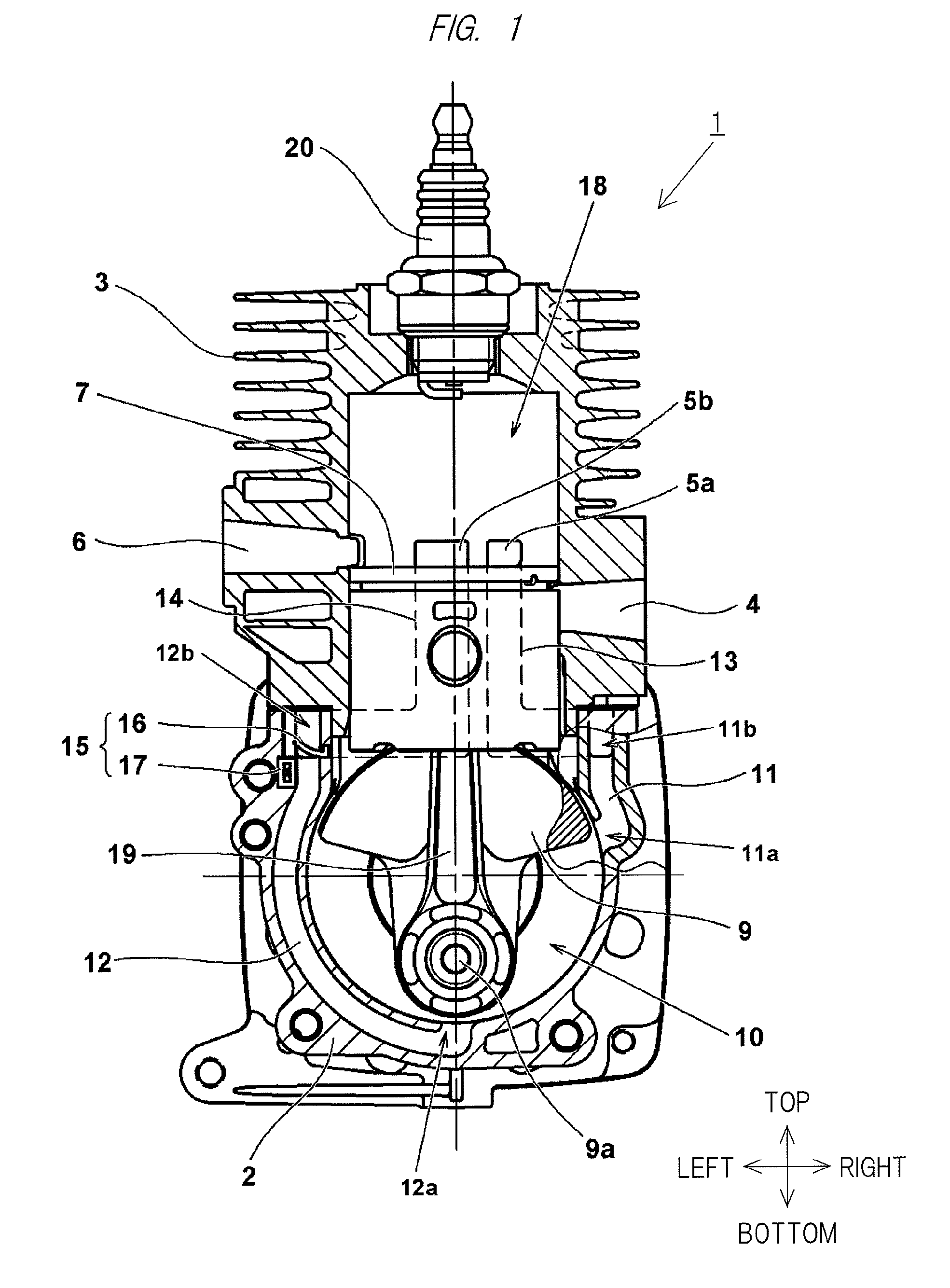
[0019]Hereinafter, embodiments of the present invention will be explained based on the drawings. Note that, in the drawings described below, the same parts as those of the conventional example shown in FIGS. 6 and 7 will be denoted by the same symbols, and repetitive descriptions will be omitted. In the present specification, front / rear, left / right, and top / bottom directions will be explained as the directions indicated in the drawings.

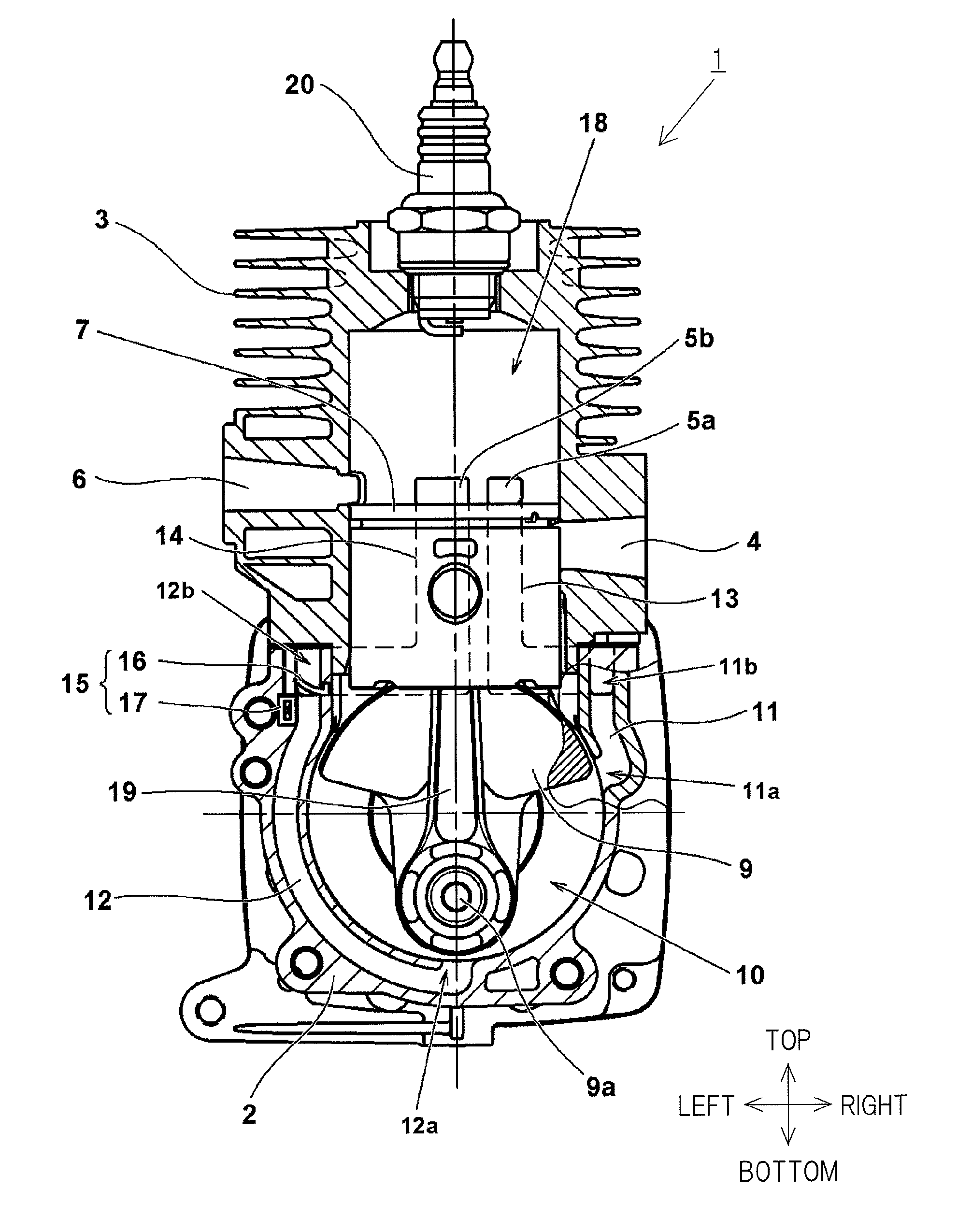
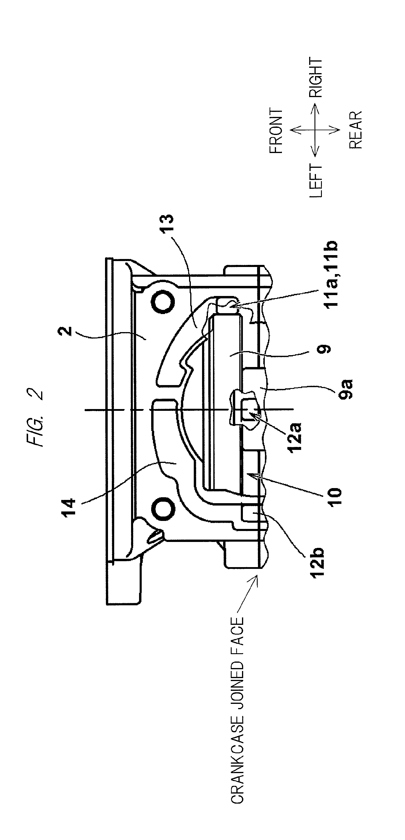
[0020]FIG. 1 is a vertical cross-sectional view showing an internal structure of an engine according to the embodiment of the present invention. A main point of the present embodiment that is different from the engine 101 of the conventional example shown in FIGS. 6 and 7 is a point that a crankcase 2 is equipped with two systems of scavenging passages (first scavenging passage 11, second scavenging passage 12). Also, another main point of the present embodiment that is different from the engine 101 of the conventional example shown in FIGS. 6 and 7 i...


PUM


Abstract

An engine and an engine-driven working machine which enable blow-though prevention of an uncombusted air-fuel mixture and control of the number of times of combustion, stabilize operation during idling, and ensure output and acceleration performance during working are provided. A two-cycle engine having: a piston; a crankcase in which scavenging passages are formed; and a cylinder in which scavenging ports communicated with the scavenging passages and an exhaust port for discharging a combustion gas are formed. In the two-cycle engine, at least two or more systems of the scavenging passages having mutually different opening / closing systems are formed in the crankcase.

Description

CROSS-REFERENCE TO RELATED APPLICATION[0001]The present application claims priority from Japanese Patent Application No. 2012-190639 filed on Aug. 30, 2012, the content of which is hereby incorporated by reference into this application.TECHNICAL FIELD OF THE INVENTION[0002]The present invention relates to scavenging passages of a two-cycle internal-combustion engine and opening / closing structures thereof and relates to an engine and an engine-driven working machine that reduce an exhaust-gas discharged volume, stabilize operation during idling, and ensure output and acceleration performance during working.BACKGROUND OF THE INVENTION[0003]As disclosed in Japanese Patent Application Laid-Open Publication No. 62-3121 (Patent Document 1), small engines, particularly, two-cycle engines are widely used as power sources in small working machines such as mowing machines and chainsaws. The two-cycle engine is capable of obtaining large output with a small size and a light weight and enables ...

Claims


Application Information

Patent Timeline
IPC IPC(8): F02B25/02
CPCF02B25/02F02B25/14F02B25/20F02B2075/025
Inventor HAGAWA, TATSUYAISHIDA, SHIGETOSHI
Owner HITACHI KOKI CO LTD
Learn More