Control device for automatic transmission
A technology of automatic transmission and control device, which is applied in the direction of transmission control, multi-ratio transmission, vehicle gearbox, etc., and can solve problems such as top impact
Active Publication Date: 2020-10-20
JATCO LTD +1
View PDF5 Cites 0 Cited by
- Summary
- Abstract
- Description
- Claims
- Application Information
AI Technical Summary
Problems solved by technology
In this case, if the automatic upshift from the 1st speed to the 2nd speed ends, the engine torque will rise and change in stages from the upper limit torque of the 1st speed to the upper limit torque of the 2nd speed at the end of the shift. The sharp rise in engine torque creates the problem of top impact
Method used
View moreImage
Smart ImageViewing Examples

Examples
Embodiment 1
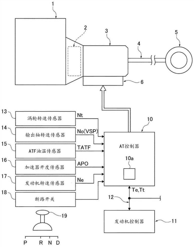
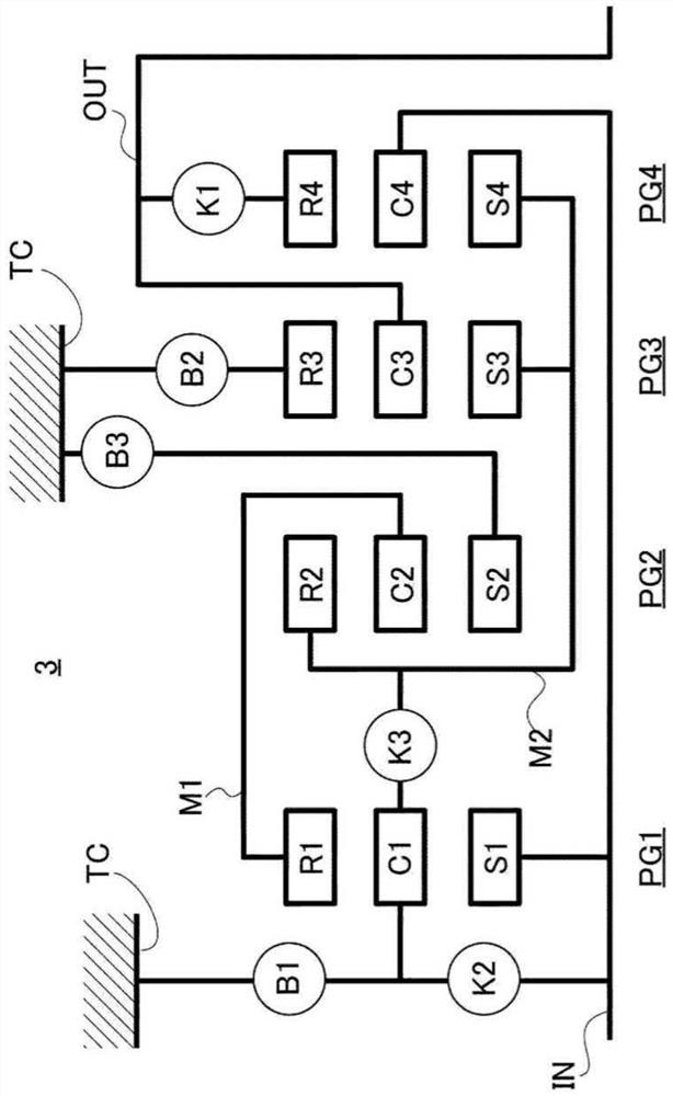
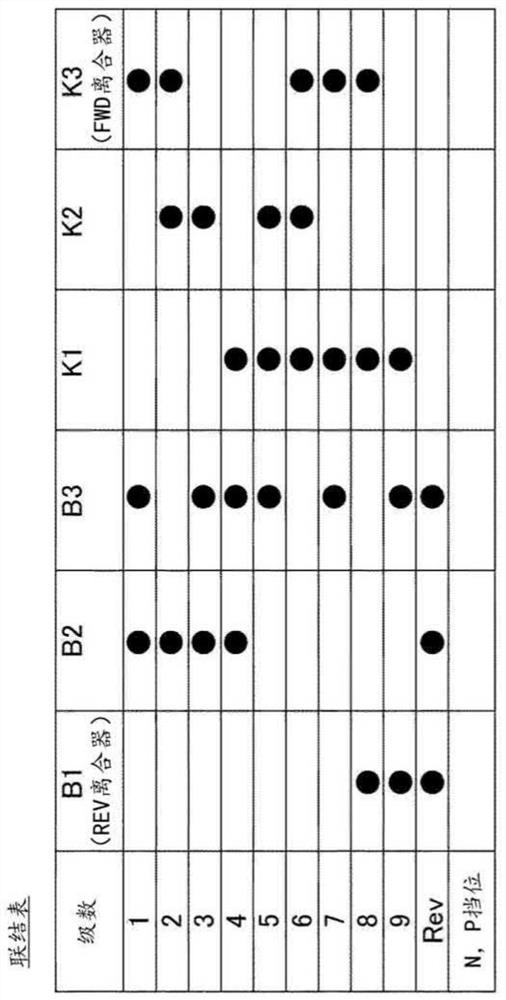
[0019] The upshift control device in Embodiment 1 is applied to an engine vehicle equipped with an automatic transmission having 9 forward speeds and 1 reverse speed. Hereinafter, the configuration of Embodiment 1 will be described as "overall system configuration", "detailed configuration of automatic transmission", and "engine upper limit torque change control processing configuration during 1-2 automatic upshift".
Login to View More PUM
 Abstract
According to the present invention a vehicle is equipped with an engine 1, an automatic transmission 3, an AT controller 10, and an engine controller 11. The AT controller 10 has an upper limit torquechange processing unit 10a which, when a 1-2 auto-upshift from the first gear to the second gear is executed in conjunction with an increase in the vehicle speed, changes the upper limit torque froma first upper limit torque to a second upper limit torque that is set higher than the first upper limit torque. When an inertia phase begins in the 1-2 auto-upshift the upper limit torque change processing unit 10a increases the upper limit torque during the inertia phase according to a prescribed gradient from the first upper limit torque to the second upper limit torque. Thus, when an automaticupshift due to an increase in the vehicle speed is executed, it is possible to suppress the occurrence of upthrust shock while maintaining acceleration performance.
Description
technical field [0001] The present invention relates to a control device of an automatic transmission mounted on a vehicle and a control method of the automatic transmission. Background technique [0002] Conventionally, there is a torque control unit that performs suppression control of engine torque when an automatic transmission is upshifted. The torque control unit describes an integrated engine and automatic transmission control device that limits engine torque to a value at the time of shift start when the upshift is a power-on upshift (see Patent Document 1). [0003] In the above-mentioned conventional device, when the upper limit torque of the second speed stage is set higher than the upper limit torque of the first speed stage of the engine torque, when the accelerator is depressed and started, the speed from the first speed stage to the second speed stage is executed due to the increase of the vehicle speed. Level automatic upshift. In this case, if the automati...
Claims
Login to View More Application Information
Patent Timeline
 Patent Type & Authority Applications(China)
IPC IPC(8): F16H61/04B60W10/04B60W10/06B60W10/11
CPCB60W10/06B60W10/04F16H61/04B60W10/11F16H2061/0492F16H2063/508B60W30/19B60W2710/0666B60W2710/1005F16H61/684F16H2200/0065F16H61/682
Inventor 松尾克宏
Owner JATCO LTD