Top of rail resilient bar

a resilient bar and rail technology, applied in the field of apparatus, can solve the problems of incompatibility of certain types difficulty in manufacturing certain applicators used in the prior art, waste of friction modifying materials, etc., and achieve the effects of reducing composition volume, reducing composition spillage, and reducing surface area

Active Publication Date: 2014-03-06
L B FOSTER RAIL TECH INC
View PDF9 Cites 12 Cited by
  • Summary
  • Abstract
  • Description
  • Claims
  • Application Information

AI Technical Summary

Benefits of technology

[0013]More than one applicator may be installed against the rail in series, each applicator in fluid communication with a reservoir and pump. Furthermore, each of the one or more applicators may comprise one or more than one exit ports. With this configuration, reduced volumes of composition may be delivered from each exit port to the rail surface, resulting in reduce spillage of the composition from the applicator. Furthermore, by having multiple sites for the delivery of the composition to the rail surface, the transfer of the composition from the rail surface to the wheel may be more efficient with a larger surface area of the wheels receiving the composition, than when using one applicator with one exit port.

Problems solved by technology

Depending upon the composition being applied, and the type of applicator used, friction modifying material may be wasted as the wheel passes along the rail and interacts with the application device.
Applicators comprising a neoprene foam may be incompatible with certain types of friction modifying materials, including water-based and oil-based compositions.
In addition, certain applicators used in the prior art may be difficult to manufacture.

Method used


Image

  • Top of rail resilient bar
  • Top of rail resilient bar
  • Top of rail resilient bar

Examples


Embodiment Construction

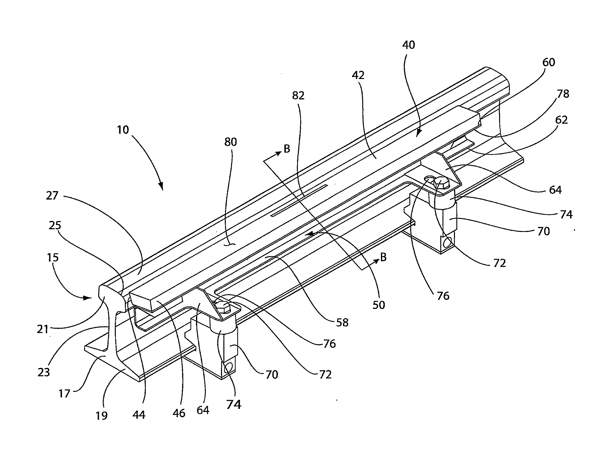
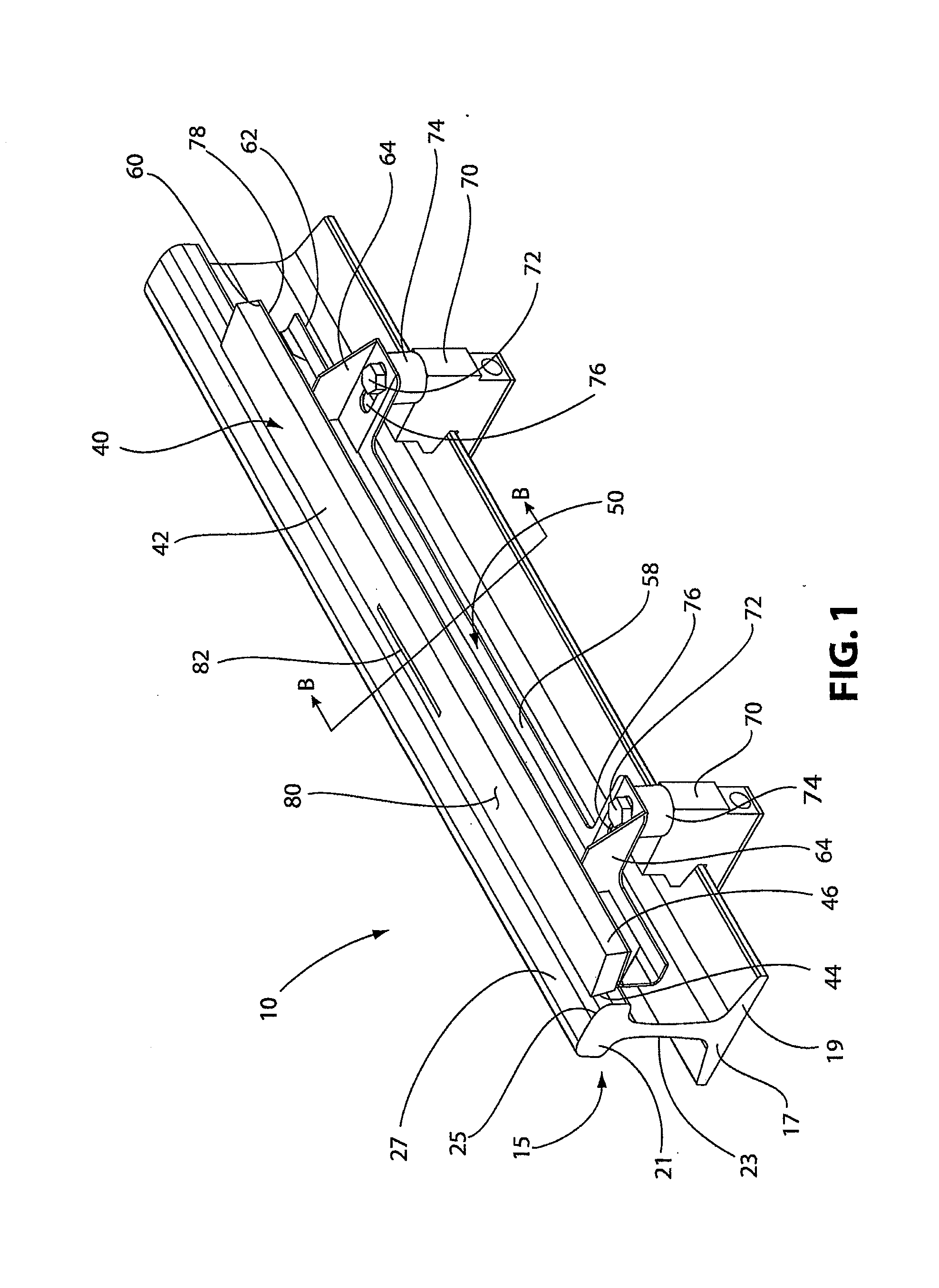
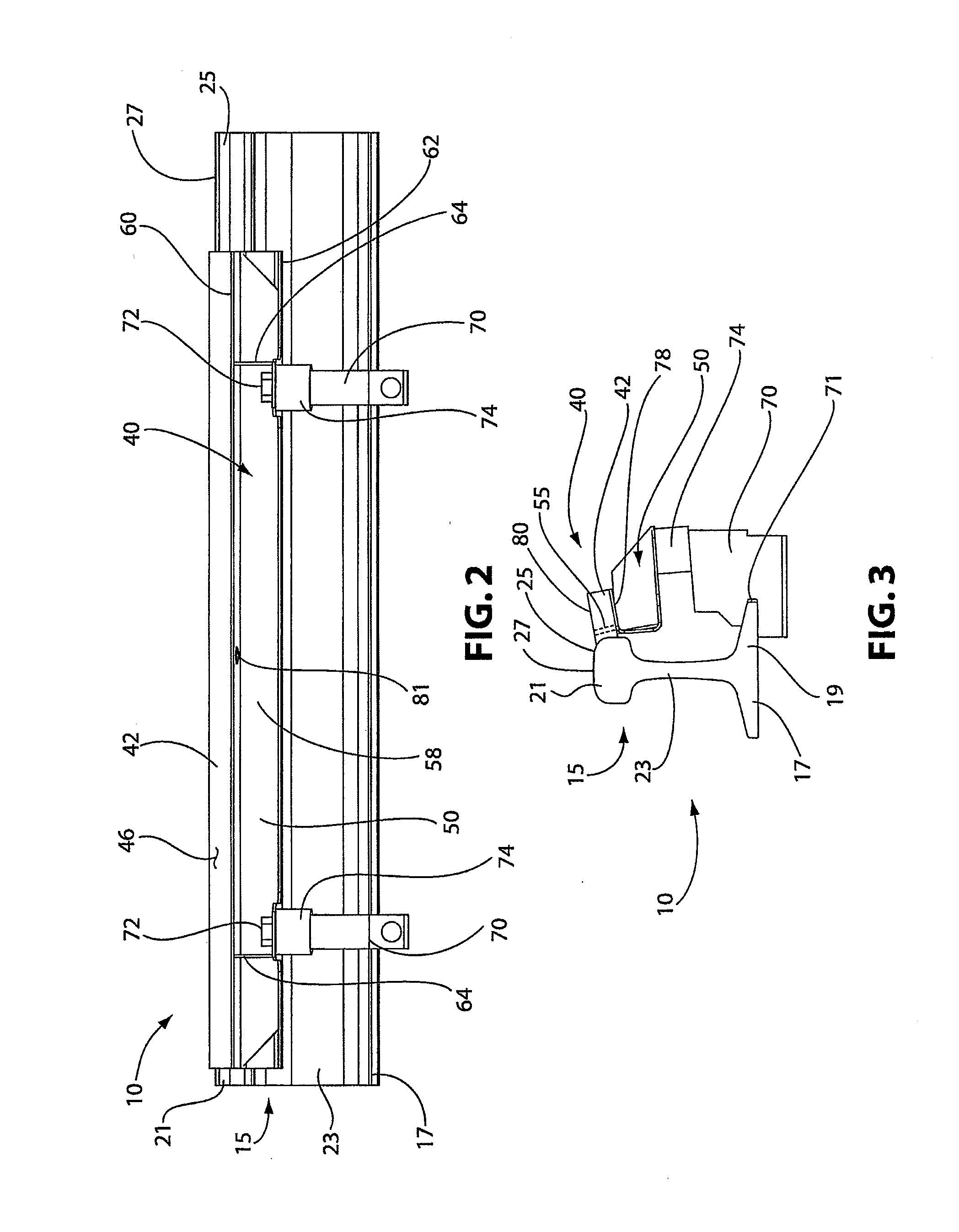
[0038]This invention relates to an apparatus for applying compositions to railroad rails.

[0039]For the purposes of the description hereinafter, spatial orientation terms, if used, shall relate to the referenced embodiment as it is oriented in the accompanying drawing figures or otherwise described in the following detailed description. However, it is to be understood that the embodiments described hereinafter may assume many alternative variations and embodiments. It is also to be understood that the specific devices illustrated in the accompanying drawing figures and described herein are simply exemplary and should not be considered as limiting.

[0040]Referring to Figures, a rail applicator assembly 10 is shown. The rail applicator assembly 10 includes a railroad rail 15 and an applicator 40 for applying a composition, for example a friction modifying material or a lubricant material, to the rail 15. The rail 15 includes a base portion 17 with flanges 19 extending therefrom and a he...


PUM


Abstract

An applicator for applying a friction modifying material to the surface of a rail is provided. The applicator comprises a resilient body for applying a composition to a surface of a rail. The resilient body comprises an outer impervious surface and defines a sealed passageway that extends through the resilient body for the composition to flow through; and an applicator support, wherein the resilient body is secured to the applicator support. A rail applicator assembly and methods for using the applicator are also provided.

Description

[0001]This application is a Continuation-in-Part of U.S. application Ser. No. 12 / 788,971 filed 27 May 2010, which claims the benefit of U.S. Provisional Application No. 61 / 182,217 filed 29 May 2009, which applications are incorporated herein by reference. To the extent appropriate, a claim of priority is made to each of the above disclosed applications.FIELD OF THE INVENTION[0002]This invention relates to an apparatus for applying compositions to railroad rails.BACKGROUND OF THE INVENTION[0003]In the operation of railroads, grease or friction modifying compositions are applied onto railroad rails, such as to the top of rails or sides of the rails at curves, turnouts, switches. Compositions that include lubricants and friction modifying materials, such as grease, can either reduce or increase the friction where necessary to improve train performance and reduce wear on both the rails and the train wheels. Some compositions, for example friction modifying materials, that increases the ...

Claims


Application Information

Patent Timeline
Patent Type & Authority Applications(United States)
IPC IPC(8): B61K3/00
CPCB61K3/00E01B7/26
Inventor APPLEBY, GLENREDFIELD, MATTHEWSCHNORR, CHARLESPETRIE, CHARLES A.
Owner L B FOSTER RAIL TECH INC
Why Eureka
Try Eureka